Introduction: How to Use I2C LCD With VIsionFive Using Python


I2c LCD is a very common display nowadays. It uses an I2C communication protocol which reduces the number of wires by just relying on two wires,
SDA (Serial Data Line)
SCL(Serial Clock Line)
It basically uses the idea of the Slave and master device concept. In which, one device act as the master and the others act as a slave. Several devices can be connected to one master using only two lines. It uses the address system. Each device connected to the system has its specific address which is used to recognize that particular device.
16x2 LCD
16x2 means 16 characters and 2 lines. This LCD is very common and is now specially designed to interface with microcontrollers and other things. The being barebone uses 16 pins but the I2c module gives them this power two utilizing two lines for data and clock while two for power. I also have one and I wanted to interface it with my VisionFive board which is Single Board Computer specially designed to run Linux.
So Let's dig into it.
Supplies
Things that we are going to need:
- VisionFive board
- 16x2 LCD using an I2C module
- Female to Female jumper wires
- Github-----------All required Files
Step 1: Circuit Diagram
It's a really simple diagram. All you have to do is to connect the SDA of LCD to the SDA of VisionFive which is at GPIO48 or physically at pin number 3. And SCL of LCD to the SCL of VisionFive which is at Pin number 5. Connect VCC to the 5v line of VisionFive and ground to the ground.
................Connections...........................
LCD--------------------------------VisionFive
SDA..........>>>>...................Pin 3
SCL..........>>>>...................Pin 5
VCC.........>>>>....................5V Line
GND.........>>>>...................GND
Now we can do some commands to get the address of the LCD.
Step 2: Setting Up Software


We are going to need a Library for I2C LCD that I luckily found at Recantha. This library allows us to Interface LCD with Python. It was designed to interface this LCD with raspberry pi but we can use it too. I updated this library a little bit to which I'll provide the link.
We need to save the library as a .py file and in the same directory as our main script.
After this we can easily import it as we do for other libraries, like
import <file_name_which_you_gave_to_it>
If your LCD is connected to your board then we can check its address by following the commands,
sudo i2cdetect -l
This will show all the lines using the I2C protocol.
We can detect the specific device connected to Bus line 1 since it was mentioned in pinout that we are connecting to I2C-1, so we can now,
sudo i2cdetect -y -r 1
It will give us the addresses of all the devices connected to that line. 0x27 in my case.
Now since we have the address now we will replace it with the address given in Library.
Open the Library File using IDLE, and replace the pre-written value corresponding to the Address.
Change the Bus line number if needed but it won't be needed. Anyways,
Now you can run the example script that is provided with this library on my Github page.
You can run the script in two ways, either by command line or by opening the file with IDLE and then running it using the python shell.
You can even use the 4-line LCD as it was written for that type of LCD. But I used it with 2 lines LCD.
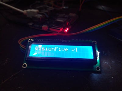
Step 3: It's Done
You can watch the demonstration video. All links to files are provided if you have any questions, feel free to ask them. I'm open to all of your kind and Humble Suggestions.


