

Introduction: How to Make a Homemade Railgun


These are brief instructions on how to make a homemade railgun.
In order to make this project, it is necessary to work with high voltages, so don't even think about making a project like this unless you are familiar with electricity, especially capacitors.(ie. Don't blame me if you hurt yourself)
If you ask a question I'll try and answer it.
I made this for my science fair project in order to see how efficient I could make a railgun (not very). See this here:https://www.instructables.com/id/1kJ-Railgun/
If you want to see video of this its on youtube: https://www.youtube.com/watch?v=HNhfc-MJg2M
Step 1: Making the Actual Railgun


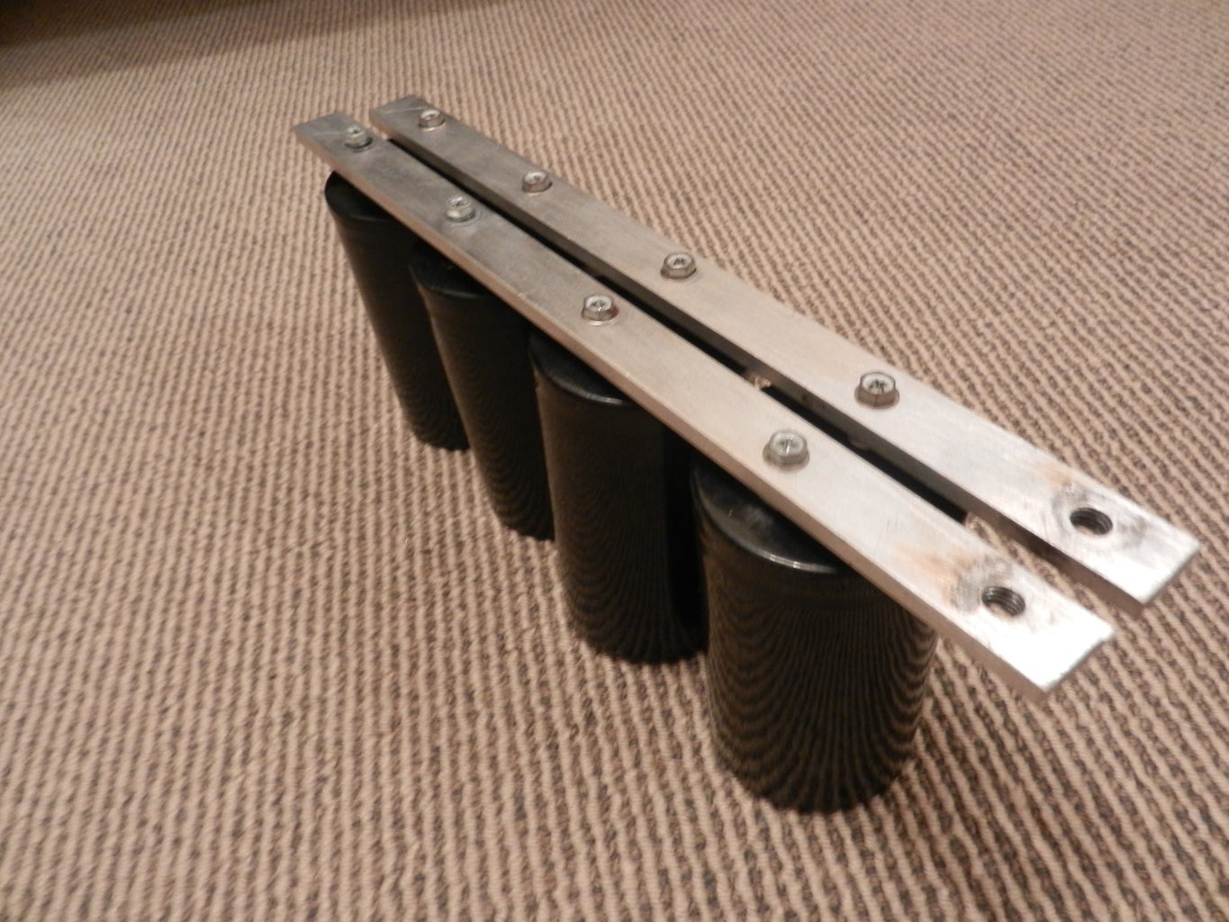
Ok, so this involves actually making the railgun. So, my one essentially consists of rails sandwiched between two sheets of perpex. The first photo shows this. You can see on the sides two extra sheets of perpex next to the aluminium rails. This was initially meant to make the railgun stronger, but in hindsight was unnecessary.
I used 6x20mm aluminium, and 6mm perspex.
This top down photo shows the "fake" perspex rails on the right, and the aluminium rails on the left. If you don't get how this works, i'll explain it at the end.
The transition from the perspex rails to the aluminium rails needs to be smooth so sand it lightly.
There really needs to be a close tolerance of the projectile fitting inside the barrel. I had a bore of 6mm, which made it easy to use the 6mm aluminium as a spacer to make sure the gap was 6mm all the way down.
Step 2: Attaching the Cables

This is not the ideal way to attach the wires, as not the greatest surface area, but it is the easiest.
I used 25mm copper wire and some lugs.
Step 3: Injection System-1

I used some hose to connect my air injection system to the railgun, just to give myself some distance from it. I simply glued the hose to a piece of wood which is screwed on.
The mesh is there to stop the projectile falling into the hose.
Step 4: Injection System-2


Right, so the first picture shows the end of the pressure chamber where air compressor goes on.
Just use a bike valve, drill a hole and just some glue.
Make sure the adhesive you use to secure the PVC endcaps is rated for pressure.
The other end is much harder. I used a 15-15mm nipple to connect the ball valve to the pressure chamber. It was quite difficult to make this seal airtight, so I used a layer of rubber on the inside with lots of cheap epoxy. Also make sure you use teflon tape to seal the threads. I just glued the hose in.
Step 5: Capacitor Bank (be Careful)
I used 4x3900mF caps rated to 450V. Connect them in parallel using either copper/aluminium busbar.
Step 6: Resistor/Bleeder Resistor

Here I just wired up two lightbulbs to a lightswitch each.
One of the was to put the charging circuit so I had a switch to start and stop charging, and so there was some resistance in the charging circuit.
The other one was also hooked up the capacitors to use as a bleeder resistor if anything went wrong (Lots of diagrams to come later).
Step 7: Projectile

I used a piece of 6mm aluminium as it fitted nicely. Just needs some light sanding so that it slides smoothly.
Step 8: Diagrams/Pictures of the Whole Thing


Well here is some stuff that I made for my science fair presentation if it helps anyone.
The board is there to work out velocities for my experiment (https://www.instructables.com/id/1kJ-Railgun/)
1. Board with lines of masking tape in 10cm increments.
2. Perspex enclosure for rail gun
3. Aluminium rails
4. Perspex ‘fake’ rails
5. Voltmeter measuring voltage across the capacitors
6. PVC pressure chamber with ball valve
7. Foot pump with PSI gauge
8. Thick 25mm cables
9. 15.6mF capacitor bank
10. Variable power supply, 0-390V DC
11. Light bulb 1
12. Light bulb 2 (bleeder resistor)
13. Switch 1
14. Switch 2
15. 120fps camera
16. Aluminium projectile
17. Hose
Step 9: Quick Rundown
I also wrote this quick explanation for my science fair if anyone wants it:
How it works
The aluminium projectile is pushed down the barrel, in between the two fake Perspex rails (4). With the projectile in this position the railgun is circuit is not complete, allowing the capacitors to be charged.
The DC power supply (10) is connected to the capacitor banks. When the power supply is switched on, it places a voltage across the capacitors which the capacitors store. When the capacitors reach the desired voltage as measured by the voltmeter (5), switch 1 (13) is pressed to stop the charging.
The ball valve of the pressure chamber (6) is closed, and 20 psi is pumped into the chamber as measured by the pressure valve.
The camera (15) is made to begin recording at 120fps.
The ball valve is opened by hand as quickly as possible. Air flows through the hose (17), into the rail gun, which pushes the projectile forwards.
Eventually the projectile comes into contact with the conductive aluminium rails (3). At this point the circuit is complete, and the capacitors discharge. A large current passes through the rails, which should result in a force of the projectile (as explained in ‘Concept’).
Because the projectile passes in front of a board with 10cm increments on it (1), the velocity of the projectile can easily be determined by reviewing the high speed footage.
The purpose of lightbulb 2 (12) is as a bleeder resistor. In the event that the railgun misfires, and the capacitors are charged to a dangerous voltage, the capacitors can be safely discharged by pressing switch 2 (14). This allows the energy in the capacitors to be discharged through the lightbulb.
The air injection system (6) is required so that the projectile contacts the rails with some initial velocity. Otherwise, there is a significant chance that the projectile may be spot-welded to the rails.

Participated in the
Weekend Projects Contest


