

Introduction: How to Make an Arduino Based Night Light With Infrared Remote Control!


Here is an Instructable that will show you how to build an Arduino based night light with
a small infrared remote that lets you scroll through 10 pre set colors , and a random fading
color routine that loops forever.
This instructable assumes you :
Have a Arduino.
Have a soldering iron and can solder.
Can create a circuit board etched, machined or however you want.
Can build an enclosure machined, pre-made - reused, folded up paper whatever.
Can have fun looking at shiny leds!
Because we are working with electronics and machines for fabrication, I cannot be held
responsible for anything that happens while you are attempting to re-create this Instructable.
So that being said lets make something cool.
Step 1: Parts


1. Arduino I used the Duemilanove with the ATmega 168 the code is just under 7k.
2. PCB manufacturing supplies This Instructable will not show you how to make the board, there are other great Instructables already written for that. The board for this is just under 2.5" square
3. Component parts for nightlight pcb:
1 ATmega 168 Mouser # 556 - ATMEGA168P - 20PU
1 28 pin IC socket Mouser # 571 - 1 - 390261 - 9
1 2.1mm Power Jack Mouser # 163 - 4302 -EX or scavenged
1 1N4001 diode Radio Shack or scavenged
1 16 Mhz crystal Mouser # 815 - ABL -16 - B2
1 NPN IR Photo transistor Mouser # 859 - LTR3208E Digikey # for side style160-1065-ND
2 10K resistors Mouser # 291-10K-RC
4 82 Ohm resistors Mouser # 291-82-RC
2 150 Ohm resistors Mouser # 291-150-RC
2 22 pf capacitors Mouser # 140-50N2-220J-TB-RC
2 100uf capacitors Scavenged
3 100nf capacitors Scavenged
1 Momentary push button Scavenged
1 7805 5 volt regulator T0-92 package or TO-220 Mouser # 595-UA78L05ACLP or scavenged
4 RGB leds Mouser # 604-WP154A4-RGB common cathode
For common anode Adafruit Industries
Component parts for remote:
1 2N3904 NPN transistor Radio Shack or scavenged
1 2N3906 PNP transistor Radio Shack or scavenged
1 Momentary push button Radio Shack or scavenged
1 100nf capacitor Radio Shack or scavenged
1 IR emitter Mouser # 859-LTE-3271BL
1 1Mohm resistor Radio Shack or scavenged
1 22K resistor Radio Shack or scavenged
1 paper clip Scavenged
Note on IR Transistor and emitter. They can be bought in pairs at Radio Shack.
4. 5volt - 9volt wall wart.
Make sure its center positive polarity, and has a 2.1 mm plug.
You can definitely find a suitable wall wart at the thrift store or use an old cell phone charger.
If you need to get the 2.1 mm plug you can get it through Mouser or Radio Shack, just make
sure you wire it up center positive. If you cant find one and you have to buy a new one Adafruit, or
Sparkfun both carry one that will work. If you have one and need to change the polarity check this out.
5. Materials for enclosure:
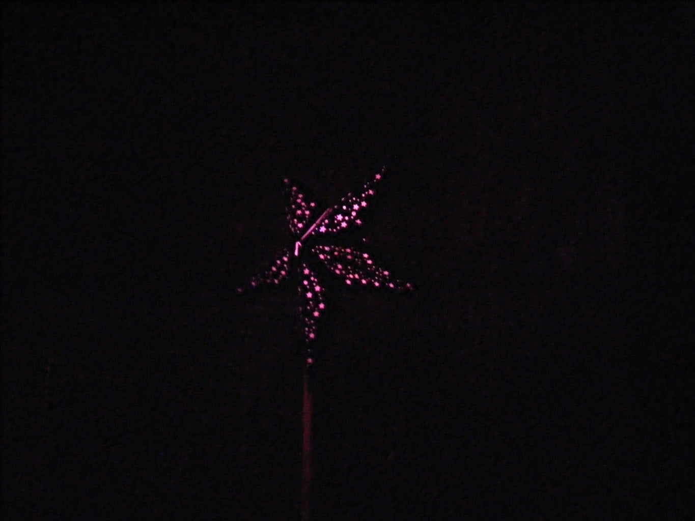
These can be whatever you choose as long as it defuses the light from the leds in a way
you like. A couple of enclosures I chose were a pre-made star lamp that was intended for an
incandescent light bulb, a piece of 81/2 x 11 printer paper folded into a box shape, and some aluminum and clear plastic that I machined into a shape that was similar to the pcb.
Step 2: Program the Chip
Here is the code!
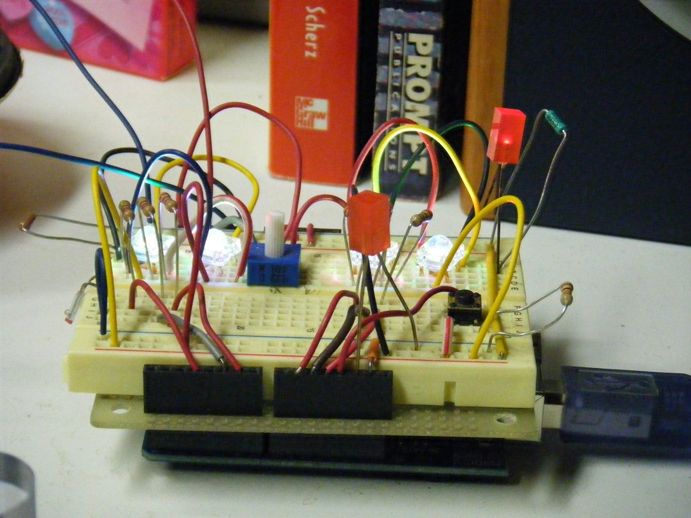
For this step my advice is if you already have the RGB leds, you should breadboard the circuit and see if
it is something you want to continue to build. If it is or you already know you need to have it continue on!
(When you download nitelite.pde it will download as a .tmp file, to load it into the
Arduino IDE create a folder called nitelite in your arduino projects folder and re-name the .tmp file
nitelite.pde and put it in the nitelite folder.)
Attachments

Step 3: Build and Populate the Pcbs


Decide which one of the boards you want to build according to the parts on hand and go for it.
I've included eagle files of both the common anode and common cathode version, as well as the remote. The same code works on both of the boards but there are color differences due to the hardware being different. I think both the versions look great.
Step 4: Build the Enclosure Final Assembly


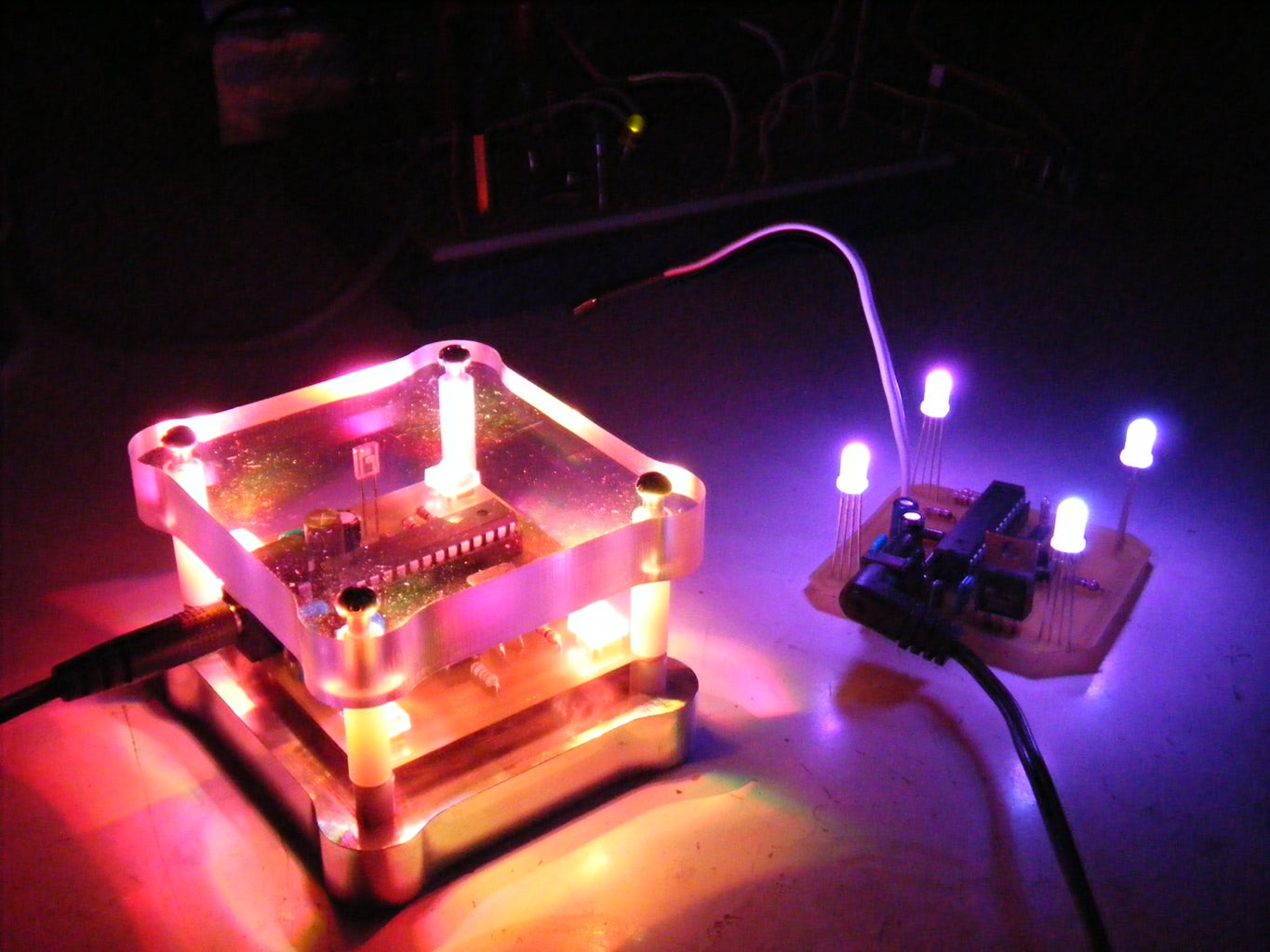
Whatever enclosure you decided to build or use for your night light pulls it all together for the
finished project. Ive uploaded several examples from easy to not so easy (unless you have access to a CNC machine) . I've also included a short video of the remote changing the settings and the
fade routine. I hope you are inspired to go for it.
enjoy!
Participated in the
Microcontroller Contest

Participated in the
3rd Epilog Challenge


