Introduction: How to Program the ATtiny85 With the Arduino Uno Board
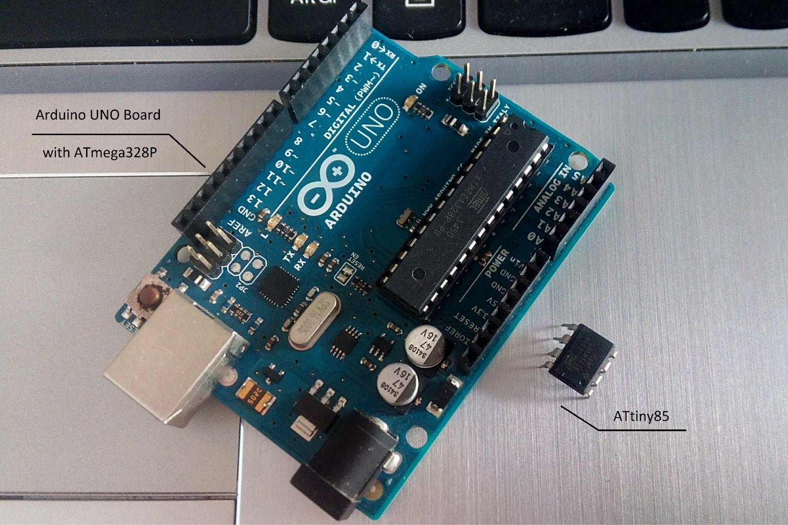


In this tutorial we will use an Arduino board as an ATtiny programmer.
To do this we will use one Arduino UNO board as an ISP (programmer) and one ATtiny85 micro-controller.
We will use Codebender - online Arduino IDE.
With the following procedure you will be able to program easily the ATtiny45 and ATtiny85 micro-controllers.
So, let's get started!
Step 1: What You Will Need
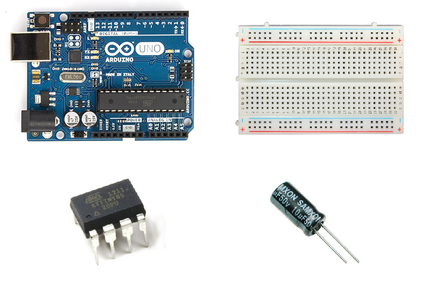
For this tutorial you will need:
- Arduino uno
- Breadboard
- ATtiny85
- 10 uF capacitor
- jumper wires
Step 2: About the ATtiny85
From Atmel:
The high-performance, low-power Atmel 8-bit AVR RISC-based microcontroller combines 8KB ISP flash memory, 512B EEPROM, 512-Byte SRAM, 6 general purpose I/O lines, 32 general purpose working registers, one 8-bit timer/counter with compare modes, one 8-bit high speed timer/counter, USI, internal and external Interrupts, 4-channel 10-bit A/D converter, programmable watchdog timer with internal oscillator, three software selectable power saving modes, and debugWIRE for on-chip debugging. The device achieves a throughput of 20 MIPS at 20 MHz and operates between 2.7-5.5 volts.
Datasheet: download
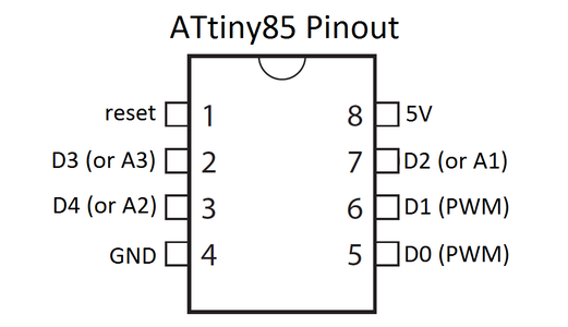
ATtiny85 pinout
- Pin 1 - reset
- Pin 2 - digital pin 3 / analog pin 3
- Pin 3 - digital pin 4 / analog pin 2
- Pin 4 - gnd
- Pin 5 - digital pin 0 (PWM)
- Pin 6 - digital pin 1 (PWM)
- Pin 7 - digital pin 3 (PWM)
- Pin 8 - Vcc (2.7~5.5V)
Step 3: Arduino UNO As an ISP
Here's the "Arduino ISP" code, embedded using Codebender!
Try downloading the Codebender plugin and clicking on the "Run on Arduino" button to program your Arduino board with this sketch. And that's it, you've programmed your Arduino with the ISP program!
Now disconnect the Arduino usb cable from your computer and proceed to next step.
Step 4: Connecting the Arduino Uno With the ATtiny85

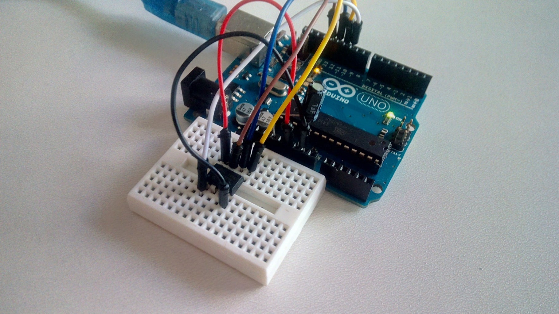
The connections are pretty easy, see the above image with the breadboard circuit schematic.
Tip: The dot in the corner of the ATtiny shows the first pin.
- Pin 1 to Arduino pin 10
- Pin 2 -
- Pin 3 -
- Pin 4 to Arduino GND pin
- Pin 5 to Arduino pin 11
- Pin 6 to Arduino pin 12
- Pin 7 to Arduino pin 13
- Pin 8 to Arduino 5V pin
Connect a 10uF electrolytic capacitor between Arduino uno reset pin and ground.
Tip: The stripe on one side of the capacitor shows the negative pin and should connected with ground.
We will use the capacitor because it prevents the Arduino UNO from resetting, so we are sure that the Codebender (or Arduino IDE) talks to the ArduinoISP, and not with the bootloader, during the upload of sketches.
You can now connect again the Arduino uno to your computer and proceed to next step!
Step 5: Program the ATtiny85 With Codebender

We will use Codebender - online Arduino IDE - to program the ATtiny85 micro controller. Click here to connect with your Codebender account.
New to Codebender?
Codebender is an online Arduino IDE, and free of use! Why Codebender? You can write and program your Arduino boards from your browser and the best part is that you can store all of your sketches online! So there accessible from everywhere! Also you can share them with your friends and social networks.
With 517 builtin libraries, codebender offers the most comprehensive list of Arduino libraries in the world, and you can simply include them in your projects to use them.
Click here to make your new Codebender account for free!
Make a new sketch
We will make a new sketch for the ATtiny85 that will turn on an LED. We will connect the LED with a 220 Ohm resistor to digital pin 3 (pin 2 of ATtiny85).
Click on the "Create new sketch" button.
In the void loop() we will define the D3 as an outup: pinMode(3, OUTPUT); and we will turn on an LED with: digitalWrite(3, HIGH);.
For the next steps see the image above:
- Select port (mine is COM3)
- Select from boards menu the ATtiny85 with 8MHz internal osc
- Click on advanced options button (gear icon on the right)
- Select "Arduino as ISP"
- Press the "Run on Arduino" button
That's it, you've programmed the ATtiny85 with this sketch!
Supported Arduino Commands:
- pinMode()
- digitalWrite()
- digitalRead()
- analogRead()
- analogWrite()
- shiftOut()
- pulseIn()
- millis()
- micros()
- delay()
- delayMicroseconds()
- SoftwareSerial()
Step 6: Well Done
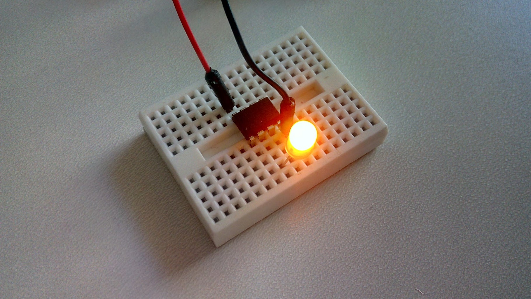
Now you can remove the "programming" wires from the Arduino uno board.
You will only need power cables from 5V and GND. You can also use a rechargeable battery 3.7V or an external power source (max 5V)
You have successfully completed one more "How to" tutorial and you learned how to program the ATtiny85 micro-controller with the Arduino uno board!
I hope you liked this, let me know in the comments.
There will be more of them, so make sure to click Follow button!
Find more useful Arduino Tutorials here.


