

Introduction: Hypercube 3D Printer (using RatRig Frame Kit)


This is a build log for the Hypercube 3D printer. The design is originally made by Tech2C (Youtube Link - Thingiverse Link).
Please note that this instructable assumes you have a little knowledge of 3D-printers and how they work. I will not go into details on how to set-up the firmware etc. Much information can be found in the Youtube videos linked above.
I strongly recommend watching Tech2C's buildlog on YouTube before building this printer, as there are some good explanations and tips in the videos.
Please note that this instructable is a work in progress. Please give comment and suggestions on how to make it more clear :)
Step 1: Parts Required


The original BOM (Bill of Material) is availible at the Tech2C Thingiverse page.
I used other bearings and smooth rods, but otherwise my BOM is quite similar.
Frame (all supplied in the kit from RatRig):
2 x 340mm V-SLOT 2020 Aluminium Extrusion
2 x 303mm V-SLOT 2020 Aluminium Extrusion
2 x 340mm V-SLOT 2020 Aluminium Extrusion
2 x 303mm V-SLOT 2020 Aluminium Extrusion
4 x 350mm V-SLOT 2020 Aluminium Extrusion
28 x 90 Degree Corner Bracket
56 x Button Head Screws M5 - 8mm
60 x Button Head Screws M5 (Single) (Length: 10mm).
116 x "Drop-in" Tee nuts
Linear movement:
2 x 8mm Hardened steel smooth rod, length 300mm (Y axis)
2 x 8mm Hardened steel smooth rod, length 360mm (X axis)
2 x 8mm Hardened steel smooth rod, length 350mm (Z axis)
10 x IGUS RJ4JP 01-08 bearings
1 x T8 300mm Lead Screw
1 x 5x8mm Aluminium Flexible Shaft Coupler
16 x F623ZZ Flange Bearing
1 x 5M GT2 Belt
2 x 2GT-20 Teeth Timing Pulley
Electronics:
4 x NEMA17 stepper motor (4000g-cm 56OZ-IN)
1 x All Metal Bowden Remote Extruder
1 x 3D Printer Controller RAMPS 1.4 Board (display board is optional)
1 x Arduino Mega 2560 R3
5 x A4988 (or DRV8825) Stepper motor driver
1 x MK3 Aluminum Heatbed
1 x High Current 210A MOSFET Upgrade (or a relay and bang-bang setting for heatbed)
3 x Endstop switch
Various Cables and dupont (female) connectors
Misc parts:
1 x 440Pcs M3 A2 Stainless Hex Head Socket Cap Screws Nuts Assortment Kit
I bought all parts for the frame from RatRig as they have a complete kit with all fixings required, except from electronics and the printed parts (Hypercube 3D kit from Ratrig: Natural Kit - All Black Kit).
You will require a 3D-printer or access to a 3D-printing service to build this printer. All my parts are printed in Torwell PETG, 0,25mm layer height, 50% infill.
If something is missing or unclear in this instructable, please let me know.
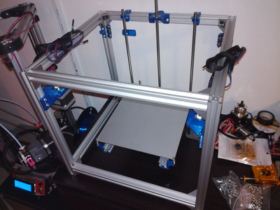
Step 2: The Frame


The parts used in the base frame are the following. These parts are all included in the RatRig kit.
Bottom:
2 x 340mm V-SLOT 2020 Aluminium Extrusion
2 x 303mm V-SLOT 2020 Aluminium Extrusion
Top:
2 x 340mm V-SLOT 2020 Aluminium Extrusion
2 x 303mm V-SLOT 2020 Aluminium Extrusion
Sides:
4 x 350mm V-SLOT 2020 Aluminium Extrusion
Fixings:
90 Degree Corner Bracket
Button Head Screws M5 (Single) (Length: 8mm)
I started to assemble the top part of the printer, following by the legs (Z-height) and finishing with the bottom. Lastly, I checked all screws one more time and tightened everything. Make sure the frame is straight and paralell.
Step 3: Mounting the Z-axis and Bed Platform


Platform:
2 x 285mm V-SLOT 2020 Aluminium Extrusion
1 x 135mm V-SLOT 2020 Aluminium Extrusion
90 Degree Corner Bracket
Button Head Screws M5 (Single) (Length: 8mm)
4 x Small springs for the bed.
Z-axis:
1 x T8 300mm leadscrew with nut
1 x 5x8mm flexible coupler
2 x 350mm smooth rods
4 x Igus RJ4JP-01-08
Printed parts:
2 x Z_Carriage
4 x Z_Carriage_Clamp
4 x Z_Shaft_Clamp
1 x Z_Nut_Mount
1 x Z_Motor
1 x Z_Leadscrew_Support
4 x Bed_Support
1 x Z_Endstop
1 x Z_Endstop_Adjust
Assemble the build platform.
Then, mount the Z-carriages and bearings. Also mount the Z nut mount in the middle on the small aluminum extrusion on the platform. See images.
Place the Z-motor mount in the bottom middle and mount the motor and threaded rod. Also mount the leadscrew support in the top. Make sure these are aligned.
Use the assembled bed platform to position the Z-axis rods and mount them to the frame.
Mount the bed supports and the heatbed.
Finally assemble and mount the endstop holder and the endstop adjust. The height of the endstop will be adjusted later on.
I had to adjust my build platform after I noticed that it was positioned to far to the back of the printer. See the detailed images on the Z-carriages.
Step 4: X/Y Motors, Idlers and Y-shafts


Idlers:
8 x F623ZZ flanged bearings.
2 x 300mm smooth rod for Y axis.
4 x IGUS RJ4JP 01-08 bearings (used in XY joiner, next step).
Printed parts:
1 x XY_Motor_Left
1 x XY_Motor_Right
2 x XY_Idler
3 x Y_Shaft_Clamp
1 x Y_Shaft_Clamp_Left_Motor
Mount the bearings for the XY joiner on the smooth rod, and then insert the smooth rod in the Y shaft clamps and mount the clamps to the frame. Note that the clamp on the front left is a little different. This is because the motor mount has slot that the Y-shaft clamp fits in. It also shares one screw.
Mount the 2 motor mounts and mount the motors in place.
Assemble the 2 idlers with bearings (F623ZZ) and mount the on the inner sides of the rear vertical aluminium extrusions.
Step 5: Mounting the X-shafts and X-carriage


Parts:
8 x F623ZZ flanged bearings.
2 x 360mm 8mm hardened steel smooth rod for X axis.
2 x IGUS RJ4JP 01-08 bearings.
Printed parts:
2 x XY_Joiner
1 x X_carraiage
1 x X_carriage_beltclamp
I use 8mm smooth rods for the X-axis. As the original design uses 10mm aluminium tubes, you will have to print other XY Joiners, these are linked from the Hypercube Thingiverse page, direct links: XY joiner 8mm - Clamp for bearings.
As the IGUS bearings are very slippery on the outside, I added one round of electrical tape around them (make sure it's even!). This prohibited slipping of the bearings. Be careful not to tighten the bearing clamps to hard as the bearings will be stuck on the rods!
When you have mounted the XY joiners and the X-carriage, mount the belts. For more details on how to mount the belts. You may have to adjust the tension of the belts later on.
Step 6: Mounting the Hotend and the X-endstop

Parts:
1 x E3D V6 J-head hotend
1 x Endstop
Printed parts:
1 x E3D_Mount
1 x E3D_Clamp
First mount the X-endstop to the X-carriage. If you want to be able to switch tools later on, make sure you separate the wires for the endstop from the wires to the hotend.
The mounting of the hotend to the X-carriage is quite straight forward. Put the nuts in the E3D_Mount, and put 4 screws in the carriage. Use the clamp and 2 screws + 2 nuts to clamp the hotend to the mount.
Step 7: Y- and Z-endstops


Parts:
2 x Endstops
1 x Spring
Printed parts:
1 x Y_Endstop
1 x Z_Endstop
1 x Z_Endstop_Adjust
Mount the Z-endstop to the left Z-axis, then mount the Y-endstop to the left Y axis, in the slot in the motor mount.
Assemble the Z-endstop with the spring and the screw, and mount it on the bed holder. Move the bed so that the hotend nozzle rests on the heatbed, and adjust the endstop so it triggers at this point. You will have to fine-tune this once everything is wired up.
Step 8: Wiring the RAMPS
Parts:
1 x RAMPS 1.4 board
Cables
The wiring of the ramps is very similar to a Cartesian (i3) printer. See this image (from RepRap Community). For details on the RAMPS board, see this page.
The stepper drivers have jumpers to select which mode to use. I use 1/16 microstepping. You will have to check your stepper driver on how to set these jumpers. For the A4988 or DRV8825, see this page.
If X and/or Y moves the wrong way, just turn the connectors for the stepper motors on the RAMPS board.
Please note: The RAMPS board cannot handle the current required for the heatbed (my burned..). I use a separate relay for the heatbed, but you can also use a MOSFET transistor board.
Step 9: The Extruder

There are different types of extruders and different mounts on what you choose. I use a simple one without any gear reductions, as my stepper motors are strong enough to handle the torque required. The mount I use for the extruder motor is this one.
If your extruder moves the wrong way (extruder retracts filament), just turn the motor connector.
Step 10: Uploading the Firmware
Make sure you have the Arduino IDE installed on your computer.
Download the Marlin firmware from this page.
Unpack the Marlin firmware. Replace the configuration.h file with the file from the Tech2C Thingiverse page. I do not use any autolevel sensor, but if you do you will have to choose the file with sensor.
Open the Marlin file and check your temperature sensor types, steps per mm and so on. If you use a relay for the heatbed, you will have to disable PID control (and use bang-bang instead). This is done by commenting out the line "#define PIDTEMPBED" in the configuration.h file.
Step 11: Print
You should now have a complete Hypercube 3D printer. You will probably have quite a few more hours to go before everything is perfect. Information on how to calibrate and adjust are all around the web. Reprap community, Facebook groups and forums are a good place to start.
And if you get tired of just printing, try to add a CNC toolhead or a laser!


