

Introduction: ICStation FM Radio Soldering Kit With LED Lights


Introduction:
Description:
It is an RDA5807 87.0MHz-108.0MHz Wireless FM Radio Receiver DIY Kit with RGB spectrum indicator flashing automatically.
It has a LCD1602 display screen which can clearly display the receiving frequency.
Feature:
- Built-in volume adjustment
- RGB spectrum indicator flashing automatically
- Support 87Hz-108MHz receiver frequency
- Built-in 5W power amplifier
- LCD1602 display screen
Parameter:
- Product Name:RDA5807 FM 87-108MHz Radio Receiver LCD1602 DIY Kit
- Work Voltage:DC 4.5V~5.5V
- Output impedance:4ohm
- Output power:5W
- Output channel:Mono
- Receiver Frequency:87.0MHz~108.0MHz
- Frequency accuracy:0.1MHz
- Equivalent noise: >=30dB
- Work Temperature:-40℃~85℃
- Work Humidity:5%~95%RH
- Size(Installed):90*70*55mm
Supplies


Practical DIY Kit
This is a radio electronics soldering kit, come with a package of electronic components and shells, users need to use soldering tools (not included) for assembly.
Perfect for electronics hobbyists and beginners to learn soldering skills and abilities while getting a practical radio.
LCD Display
Equipped with high-definition LCD screen, after the assembly is completed, you can freely adjust the frequency you want to listen to and the volume you need through the buttons below the radio.
Cool LED Lights
In addition to having the basic functions of a radio, it is also equipped with 10 LED lights, when you listen to the radio, these LED lights will randomly flash different colors of light and beat with the radio sound, making your DIY radio unique.
Great Gift
Maybe you also want to DIY a small gift ? To your friend or family member? This radio DIY electronics kit might be a good choice. It is also protected by an acrylic transparent case, which not only looks beautiful, but also protects the components inside from external damage
Attachments

Step 1: Install 1pcs SMD Components RDA5807 FM Receiver at U2

Note: PCB has 2 versions: Older version comes with blue RDA5807 receiver. Newer version comes with green RDA5807 receiver.
Step 2: Install 1pcs 10ohm Metal Film Resistor at R6

Step 3: Install 2pcs 100ohm Metal Film Resistor at R19,R20

Step 4: Install 2pcs 6.8Kohm Metal Film Resistor at R12,R15

Step 5: Install 4pcs 1Kohm Metal Film Resistor at R9,R13,R16,R17

Step 6: Install 11pcs 10Kohm Metal Film Resistor at R1-R5,R7,R8,R11,R14,R15,R18

Step 7: Install 1pcs DO-35 1N4148 Diode at D11

Step 8: Install 2pcs DO-41 1N4007 Diode at D12,D13

Step 9: Install 1pcs 11.0592MHz Crystal Oscillator at Y1

Step 10: Install 1pcs DIP-8 IC Socket at U3

Step 11: Install 1pcs DIP-40 IC Socket at U1

Step 12: Install 2pcs 22pF Ceramic Capacitor at C1,C2

Step 13: Install 3pcs 0.1uF 104 Monolithic Capacitor at C10,C12,C13

Step 14: Confirm and Identify the Installation Direction of the KA2284

Step 15: Install 2pcs ZIP-9 KA2284 LED Driver at KA2284

Step 16: Install 10pcs 5mm RGB LED at LED1-LED10

Step 17: Install 1pcs 16Pin DuPont Female Socket at LCD1602

Step 18: Install This Electrolytic Capacitor at C7

Step 19: Install Others 8pcs 4.7uF Electrolytic Capacitor at C3, C5, C6, C8, C11, C14, C15, C16

Step 20: Install 2pcs 4.100uF Electrolytic Capacitor at C4,C9

Step 21: Install 1pcs DC-005 Power Socket at J1

Step 22: Install 2pcs 5.8*5.8mm Self-locking Button at S4,S6

Step 23: Install 4pcs 6*6*20mm Black Button AtS1,S2,S3,S5

Step 24: Install 1pcs DIP-8 IC LM386N at U3

Step 25: Install 1pcs DIP-40 IC STC89C52RC

Step 26: Fix 4pcs M3*10mm Copper Pillar and 4pcs M3*8mm Screw on PCB

Step 27: Install 1pcs 16Pin Male Socket on the Back of LCD1602 Display Screen

Step 28: Plug LCD1602 Display Screen on 16Pin DuPont Female Socket

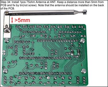
Step 29: Install 1pcs 75ohm Antenna at ANT
Step 30: Place 2pcs Red Button Cap on Self-locking Button

Step 31: Connect Speaker to PCB at SP by 20cm Red/black Cable

Step 32: Tear Off the Protective Film on the Surface of the Acrylic Shell

Step 33: Fix Top Acrylic Board and LCD1602 Acrylic Board on Copper Pillar by 4pcs M3*6mm Screw

Step 34: Fix 4pcs Side Acrylic Board by 6pcs M3*6mm Screw and 6pcs M3 Nuts.

Step 35: Fix Speaker on Acrylic Bottom Board by 4pcs M3*10mm Screws and 4pcs M3 Nuts.

Step 36: Install Speaker Acrylic Board by 4pcs M3*6mm Screw and 4pcs M3 Nuts.

Step 37: Connect to Power Supply and Enjoy the Effect


