

Introduction: JOYSTICK CONTROLLED SERVO MOTORS


In this Instructable, you’ll learn the basics of a servo motor and how to control it with a joystick. I am using the Intel Edison SoC mounted on the Arduino expansion board as the core of my project, however, any Arduino compatble board will work just fine.
Step 1: REQUIREMENTS
Arduino compatible board
Joystick
Servo Motors
Breadboard and Wires
Breadboard power supply(optional)
Step 2: WHAT IS a SERVO MOTOR?

Basically a servomotor is a rotary actuator that allows for precise control of angular position, velocity and acceleration. It consists of a suitable motor with the rotating shaft connected to a set of gears coupled to a sensor for position feedback. These motors are generally made for very high torque and have restricted rotation, in my case it’s just 180 degrees.
Servo motors have been around for a long time and are utilized in many applications. They are small in size but pack a big punch and are very energy-efficient yet have high torque while keeping the weight as low as 10g. These features allow them to be used to operate remote-controlled or radio-controlled toy cars, robots and airplanes. Servo motors are also used in industrial applications, robotics, in-line manufacturing, pharmaceutics, and food services, but how do the little guys work?
Step 3: WHAT'S INSIDE a SERVO MOTOR?


To fully understand how the servo works, you need to take a look under the hood. Inside, there is a pretty simple set-up: a small DC motor, a potentiometer (a variable resistor), and a control circuit. The motor is attached by gears to the control wheel. As the motor rotates, the potentiometer's resistance changes, so the control circuit can precisely regulate how much movement there is and in which direction.
When the shaft of the motor is at the desired position, power supplied to the motor is stopped. If not, the motor is turned in the appropriate direction. The desired position is sent via electrical pulses through the signal wire. The motor's speed is proportional to the difference between its actual position and desired position. So if the motor is near the desired position, it will turn slowly, otherwise it will turn fast. This is called proportional control. This means the motor will only run as hard as necessary to accomplish the task at hand.
Step 4: WHAT IS a JOYSTICK?


A joystick is connected to two potentiometers. Each potentiometer is used to record for left and right and forward and backward movements. When a joystick is moved these two potentiometers sends the details of the y and x co-ordinates to the Arduino and the required movement is achieved. Some gaming joysticks are equipped with another degree of freedom i.e. a Z-axis, I’ve also used this axial movement to control another servo. Note that I had to first disassemble the joystick and then remove a circuit which wasn’t needed and then I physically connected wires to +5V rail, Ground rail and the three potentiometers’ signal lines. For those of you who are not so sure how to do this can contact me at the email-id given at the end of this instructable.
Step 5: WORKING PRINCIPLE

For those of you who are familiar with the Arduino programming environment, what I’ve done is modified the “Servo Knob” program and for those who are not so familiar with Arduino this’s for you, when you move the joystick the potentiometer encodes analog voltage values and sends it to the Arduino board via the analog data pin. Next the Arduino picks up these analog values and feeds it to an ADC (analog to digital converter) which converts the analog values from the potentiometer to digital signals. Note that a Servo motor works on analog values and Arduino boards are incapable of producing analog outputs, all the output rails of an Arduino board work on digital signals, now that’s problem. You might be thinking potentiometer gives an analog output and a servo motor needs an analog input, so why don’t we just throw away the Arduino and directly connect the potentiometer to the servo right? But no folks, both of them work with a different range of analog values for which we need to use an Arduino. What the Arduino does is takes up analog values from the joystick potentiometer and maps those values for a different range of analog that’s suitable for the servo, but wait… I just said somewhere above that Arduino does not provide analog output so how do we control the servo, well, there’s something in electronics called as PWM (pulse width modulation) which is a technique for getting analog results with digital means. Digital control is used to create a square wave, a signal switched between on and off. This on-off pattern can simulate voltages in between full on (5 Volts) and off (0 Volts) by changing the portion of the time the signal spends on versus the time that the signal spends off. The duration of "on time" is called the pulse width. To get varying analog values, you change, or modulate, that pulse width. The time for which the logic level stays high is called a “Duty Cycle” which is measured in percentage and by setting the duty cycle you can disguise a digital signal as an analog signal of certain intensity. So, now I assume you might be well versed with the working principle of this apparatus. Here’s a summary, Joystick (potentiometer) - analog - ADC (Arduino) - digital (mapping) - DAC (Arduino) - PWM (pseudo analog) - Servo Motor (output).
Step 6: SETTING UP THINGS

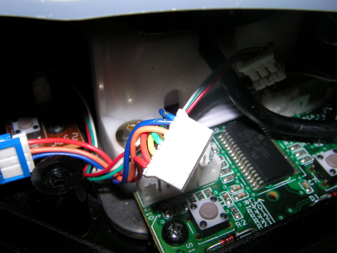
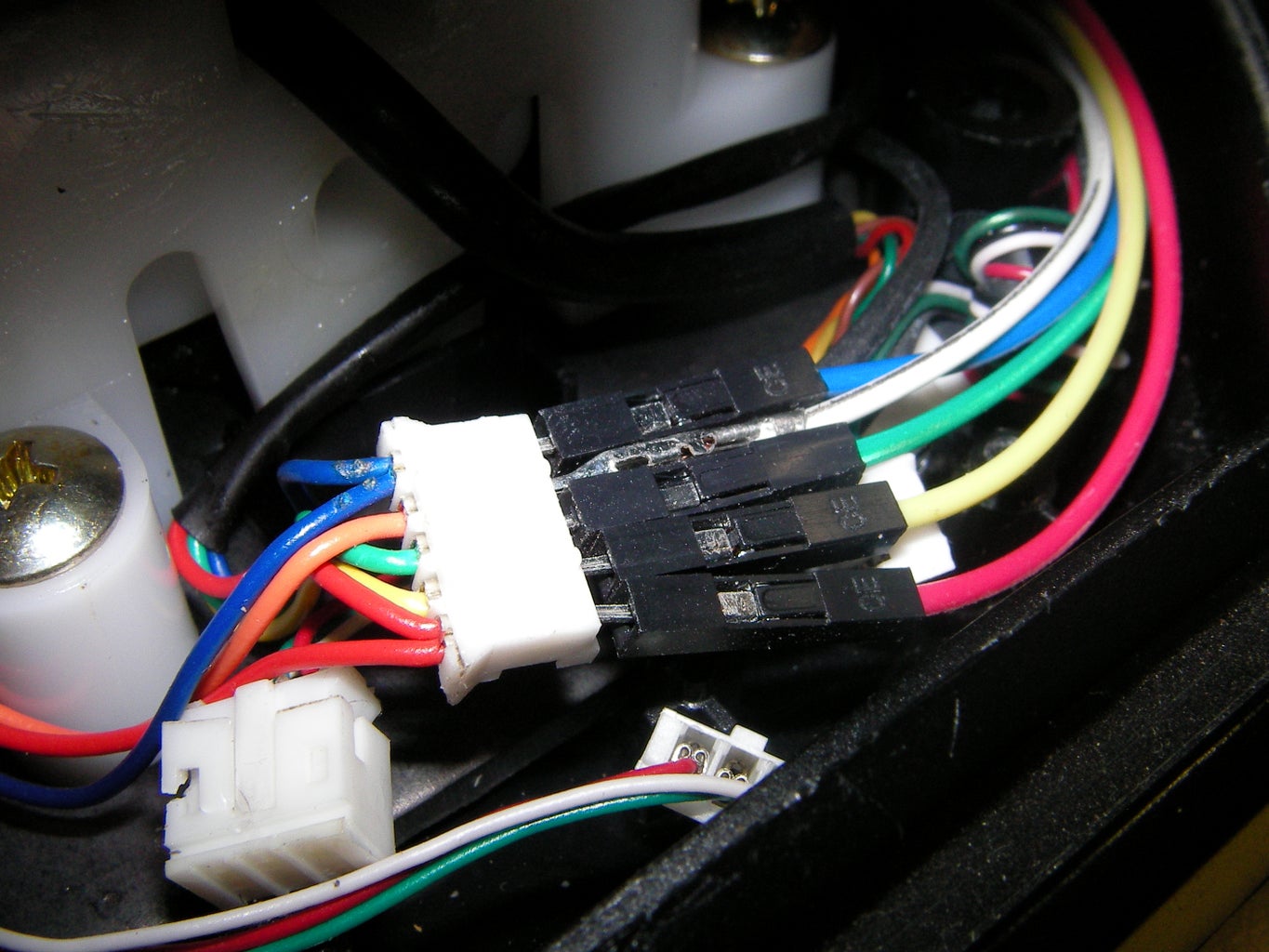


- First thing into consideration is setting up the joystick, you'll need to first open it up and check for the wires connecting the potentiometers and the +5V and the ground rail and then removing them from the circuitry and hooking up them to the Arduino. If you are not able to do so, feel free to contact me at vishalpawar1502@gmail.com
- When this is done you need to make connections as shown in the diagram just note that the potentiometers shown are not actual potentiometers, rather they are the internal potentiometers of the joystick.
Step 7: PROGRAMMING

- All the programming is done via the Arduino IDE.
- The code offers features like customisable range of Joystick and Servo motors.
- Works equally well with other Arduino compatible boards.
- Displays angular position of the Servo motors in the serial monitor, on movements of the joystick on different axes.
- The code file is provided here
Attachments

Step 8: TESTING ON DIFFERENT BOARDS


- Intel Edison on Arduino expansion board.(video-IMG_7462.MOV)
- Arduino Mega 2560.(video-IMG_7465.MOV)
- Arduino Uno R3.(video-IMG_7469.MOV)

Step 9: CONTACT AND ORDERING
- For any queries, write to me at vishalpawar1502@gmail.com
- For ordering any of the components above, visit http://www.theengineerstore.in/


