

Introduction: LED Disco Floor


This project is inspired by the Pixel Drop Ceiling by hockeyman271 and would not be possible without referencing that instructable.
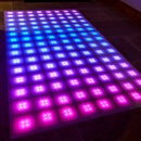
This LED Disco Floor uses WS2801 36mm RGB LEDs that are computer controlled via an Arduino. I chose the 36mm WS2801 due to their lower profile (5mm deep). This allowed me to place them alongside my floor tiles.
---------------------------------------------------------------------------------------------
ADDITION;
I have since made additional alterations to this instructable. The Arduino now runs a different program which uses the brilliant FastLED Library and doesn't require a laptop. I have added a further instruction step to the bottom of this which tells you how to do this, skipping steps 3 and 4.
Step 1: Steps 3/4 Alternative FastLED
The Arduino can be programmed with the FastLED 3.1 NoisePlusPalette https://github.com/FastLED/FastLED/tree/master/exa... There is an example video of this included above. You also need to install the FastLED 3.1 Library to the computer you are programming the arduino with. https://github.com/FastLED/FastLED
Please be sure to change the pin numbers in the program as shown in the code below.
If you use a power supply for your Arduino you can simple turn on the power to that and then the power to the LEDs and you are go!
CODE
---------------------------------------------------------------------------------
#include
#define LED_PIN 3 #define DATA_PIN 2 #define CLOCK_PIN 3 #define NUM_LEDS 120 #define BRIGHTNESS 64 #define LED_TYPE WS2801 #define COLOR_ORDER GBR CRGB leds[NUM_LEDS];
#define UPDATES_PER_SECOND 100
// This example shows several ways to set up and use 'palettes' of colors // with FastLED. // // These compact palettes provide an easy way to re-colorize your // animation on the fly, quickly, easily, and with low overhead. // // USING palettes is MUCH simpler in practice than in theory, so first just // run this sketch, and watch the pretty lights as you then read through // the code. Although this sketch has eight (or more) different color schemes, // the entire sketch compiles down to about 6.5K on AVR. // // FastLED provides a few pre-configured color palettes, and makes it // extremely easy to make up your own color schemes with palettes. // // Some notes on the more abstract 'theory and practice' of // FastLED compact palettes are at the bottom of this file.
CRGBPalette16 currentPalette; TBlendType currentBlending;
extern CRGBPalette16 myRedWhiteBluePalette; extern const TProgmemPalette16 myRedWhiteBluePalette_p PROGMEM;
void setup() { delay( 3000 ); // power-up safety delay FastLED.addLeds(leds, NUM_LEDS); FastLED.setBrightness( BRIGHTNESS ); currentPalette = RainbowColors_p; currentBlending = BLEND; }
void loop() { ChangePalettePeriodically();
static uint8_t startIndex = 0; startIndex = startIndex + 1; /* motion speed */
FillLEDsFromPaletteColors( startIndex);
FastLED.show(); FastLED.delay(1000 / UPDATES_PER_SECOND); }
void FillLEDsFromPaletteColors( uint8_t colorIndex) { uint8_t brightness = 255; for( int i = 0; i < NUM_LEDS; i++) { leds[i] = ColorFromPalette( currentPalette, colorIndex, brightness, currentBlending); colorIndex += 3; } }
// There are several different palettes of colors demonstrated here. // // FastLED provides several 'preset' palettes: RainbowColors_p, RainbowStripeColors_p, // OceanColors_p, CloudColors_p, LavaColors_p, ForestColors_p, and PartyColors_p. // // Additionally, you can manually define your own color palettes, or you can write // code that creates color palettes on the fly. All are shown here.
void ChangePalettePeriodically() { uint8_t secondHand = (millis() / 1000) % 60; static uint8_t lastSecond = 99; if( lastSecond != secondHand) { lastSecond = secondHand; if( secondHand == 0) { currentPalette = RainbowColors_p; currentBlending = BLEND; } if( secondHand == 10) { currentPalette = RainbowStripeColors_p; currentBlending = NOBLEND; } if( secondHand == 15) { currentPalette = RainbowStripeColors_p; currentBlending = BLEND; } if( secondHand == 20) { SetupPurpleAndGreenPalette(); currentBlending = BLEND; } if( secondHand == 25) { SetupTotallyRandomPalette(); currentBlending = BLEND; } if( secondHand == 30) { SetupBlackAndWhiteStripedPalette(); currentBlending = NOBLEND; } if( secondHand == 35) { SetupBlackAndWhiteStripedPalette(); currentBlending = BLEND; } if( secondHand == 40) { currentPalette = CloudColors_p; currentBlending = BLEND; } if( secondHand == 45) { currentPalette = PartyColors_p; currentBlending = BLEND; } if( secondHand == 50) { currentPalette = myRedWhiteBluePalette_p; currentBlending = NOBLEND; } if( secondHand == 55) { currentPalette = myRedWhiteBluePalette_p; currentBlending = BLEND; } } }
// This function fills the palette with totally random colors. void SetupTotallyRandomPalette() { for( int i = 0; i < 16; i++) { currentPalette[i] = CHSV( random8(), 255, random8()); } }
// This function sets up a palette of black and white stripes, // using code. Since the palette is effectively an array of // sixteen CRGB colors, the various fill_* functions can be used // to set them up. void SetupBlackAndWhiteStripedPalette() { // 'black out' all 16 palette entries... fill_solid( currentPalette, 16, CRGB::Black); // and set every fourth one to white. currentPalette[0] = CRGB::White; currentPalette[4] = CRGB::White; currentPalette[8] = CRGB::White; currentPalette[12] = CRGB::White;
}
// This function sets up a palette of purple and green stripes. void SetupPurpleAndGreenPalette() { CRGB purple = CHSV( HUE_PURPLE, 255, 255); CRGB green = CHSV( HUE_GREEN, 255, 255); CRGB black = CRGB::Black; currentPalette = CRGBPalette16( green, green, black, black, purple, purple, black, black, green, green, black, black, purple, purple, black, black ); }
// This example shows how to set up a static color palette // which is stored in PROGMEM (flash), which is almost always more // plentiful than RAM. A static PROGMEM palette like this // takes up 64 bytes of flash. const TProgmemPalette16 myRedWhiteBluePalette_p PROGMEM = { CRGB::Red, CRGB::Gray, // 'white' is too bright compared to red and blue CRGB::Blue, CRGB::Black,
CRGB::Red, CRGB::Gray, CRGB::Blue, CRGB::Black,
CRGB::Red, CRGB::Red, CRGB::Gray, CRGB::Gray, CRGB::Blue, CRGB::Blue, CRGB::Black, CRGB::Black };
// Additionl notes on FastLED compact palettes: // // Normally, in computer graphics, the palette (or "color lookup table") // has 256 entries, each containing a specific 24-bit RGB color. You can then // index into the color palette using a simple 8-bit (one byte) value. // A 256-entry color palette takes up 768 bytes of RAM, which on Arduino // is quite possibly "too many" bytes. // // FastLED does offer traditional 256-element palettes, for setups that // can afford the 768-byte cost in RAM. // // However, FastLED also offers a compact alternative. FastLED offers // palettes that store 16 distinct entries, but can be accessed AS IF // they actually have 256 entries; this is accomplished by interpolating // between the 16 explicit entries to create fifteen intermediate palette // entries between each pair. // // So for example, if you set the first two explicit entries of a compact // palette to Green (0,255,0) and Blue (0,0,255), and then retrieved // the first sixteen entries from the virtual palette (of 256), you'd get // Green, followed by a smooth gradient from green-to-blue, and then Blue.
Step 2: Parts


- Arduino Uno R3
- Arduino Proto Board
UK Plug and Cable (maybe use and old kettle lead)
36mm WS2801 LED's ( I found these cheap on Ebay from China)
- Lexan MARGARD Clear Plastic Polycarbonate Sheet 5mm (Offcuts on Ebay)
- 9mm Thick, 21mm Wide wood strips
- Translucent White Self Adhesive Vinyl
- A Windows PC/Laptop to run Jinx!
- LED Wire
The material used for the grid is entirely up to your preference, I have minimal woodworking skills but the grid structure holds up well. I was advised to try the Lexan Margard due to it's high strength and "abrasion resistance" and it has done a good job so far. The translucent vinyl was a bit of a last minute choice and I struggled to source exactly what I wanted. I was ideally after a frosted look but struggled to find one that was translucent not opaque. The amount of diffusion achieved was satisfying even with how close the LEDs are to the vinyl.
Step 3: The Circuit

The circuit was based on the Adafruit wiring diagram. https://learn.adafruit.com/36mm-led-pixels/pwiring
I used a small breadboard to split the ground connection between the Arduino and the ground wire for the LEDs. This allowed me just to have 4 wires leading down to the LEDs. The positive wire went straight to the LEDs from the power supply. I asked a qualified electrician to wire a plug to the power supply switch for me, I strongly advise consulting a qualified professional before attempting to attach a plug. Alternatively I have seen 12V power supplies in the style of a laptop charger available online.
Step 4: Programming the Arduino

In order to send the lighting effects to the LEDs I programmed the Arduino with the Glediator Sketch.
http://www.solderlab.de/index.php/downloads/category/4-glediator
Since I am connecting a laptop directly via USB to the Arduino there aren't any changes needed to Baud rates that are required for the Bluetooth communication. So, simply upload the sketch to the Arduino using the COM port it is connected to. Make sure you have selected the correct number of pixels here:
"#define Num_Pixels 120" also the pin numbers will still be:
int SDI = 2;
int CKI = 3;
Step 5: Control Software


As mentioned in the Pixel Drop Ceiling Instructable Jinx! and Glediator do a great job of controlling your WS2801 LEDs. I decided to go for Jinx! which I found really easy to set up. I didn't need to use the Bluetooth option (even though I tried) so my laptop running Jinx connects directly to the Arduino via a USB 2.0 A to B Cable.
Here are the screen shots for my set up using 120 LEDs, remember that the number of channels used is LEDs/Pixels times by 3 (R,G and B). You'll probably also spot that in the Fast Patch screen I have selected Snakelines due to the order I laid down my LEDs and that the channel order is GBR not RGB as the 36mm WS2801 are ordered Green Blue Red.
The COM port is whatever COM port that your Arduino uses which you can find out using Device Manager in Windows.
Just choose the desired effect, Click Setup > Start Output and watch your lights go. The latest version of Jinx! allows programming of multiple regions, I used this to separate 6 rectangles with the 'strobe' effect, ticked 'auto colour' and 'Audio Control' = 70's DISCO!!
On an Android Device or iPad you can use a remote desktop app to control your PC/Laptop remotely too.
Please donate if you download this software!
Step 6: Construction - Floor Grid


I chose to build a grid to surround my pixels in this project for two reasons, mainly to distribute the weight when standing on it, also to separate the light from each pixel so the colours are sharper.
We deliberately left a few tiles out in our kitchen when laying them. The area left came to 1640mm by 930mm. I had 120 pixels so the best way to lay this was 8 columns of 15. The wood used was 20mm wide which left roughly between 90 to 100mm squares around each pixel.
In order to save cutting, we placed 16 strips of wood length ways (1640mm) and then placed a smaller 98mm piece after each pixel. To allow the wires to run under the wood we cut a small gap under each piece. All the Pixels and wood were glued down using a glue gun and a lot of glue sticks!
Step 7: Construction - Lexan 'Floor'

After doing a lot of research I was advised to look into Lexan Margard, which is an 'Abrasion Proof' 'Virtually Unbreakable' transparent perspex. After consulting a friend knowledgeable about physics I bought the 5mm thick option. With the spaces in my grid being roughly 10cm squares there was easily enough weight distribution to handle chairs/high heels (so far anyway). Handily enough 5mm of Lexan also allowed for the disco floor to be level with the kitchen tiles too.
The only drawback was that the supplier I found online could only cut pieces of less than a metre which meant that I have ended up with two pieces, not ideal. I have since found a local supplier who can actually do the size I need so I will be upgrading in the future.
Step 8: Diffusion Vinyl
The last stage of this project is the diffusion material. Here I used Ritrama Translucent Self Adhesive Vinyl '5-7 Year' http://www.signmakingandsupplies.co.uk/ritrama-translucent-self-adhesive-vinyl-5-7-year-2464-p.asp this is a translucent vinyl that allowed the LED light to shine through but they aren't visible to the eye. This was fairly easy to stick on with it being self adhesive. Again there may be an upgrade to this with a frosted vinyl in the future.
Step 9: Finishing Touches
The Lexan with the translucent vinyl underneath was then placed on top of the grid and sealed round the edges with silicone.
Make sure to try out the 'Chases' in Jinx! I set up a chase of different effects that run in a sequence (what I used for the video). Jinx also allows you to alter the desktop shortcut to open with a chase (see the Jinx Manual). Add this shortcut to your start-up folder in Windows and the LEDs will start animating when Windows boots.
Please feel free to ask any questions and I will try and answer the best I can.
I'm going to enter this in to a couple of competitions on Instructables so please give me a vote!!

Grand Prize in the
Let's Party! Challenge

Participated in the
Make it Glow!


