

Introduction: Laser Refractometer


In microscopy and other sciences, it is often desirable to know the refractive index ( RI ) of transparent liquids. In a well equipped laboratory, the standard instrument for RI measurement is an Abbe refractometer, but the cost of these is well beyond the budget constraints of most hobbyists. Fortunately there is a simple low cost alternative, for transparent liquids at least. The apparatus basically consists of a hollow equilateral triangular glass prism which is filled with the test liquid. A narrow beam of light from a laser pointer is directed through the apex of the prism, and the angle through which the light beam is deviated is measured on a protractor scale. This is the principle of the prism refractometer.
It can be shown that when the deviated angle is a minimum value, the refractive index of the liquid in the prism can be calculated from the formula RI = 2 sin ½ ( d + 60 ), where d is the minimum deviation angle of the light beam. The derivation of this formula can be found in most physics text books ( for example, “Physics Part I & II” , Resnik & Halliday ( 1966 ) p 1018 ). Fig 1 illustrates the path of the beam through the prism. The minimum deviation occurs when the beam passes through the prism parallel to the base
Supplies
3 x glass microscope slides 75 mm x 25 mm
Clear Silicone Sealant ( or other suitable sealant : see below )
1 x empty CD-R container
Clear Acrylic packaging material
Double sided foam adhesive tape
1 x Protractor scale
Rigid PVC tubing, 75 mm x 20 mm diameter
MDF Board, 250 mm x 180 mm x 18 mm approx
7 x 3 mm machine screws
Aluminium bracket ( approx 15 mm x 100 mm x 1 mm thick )
1 x 1 mW Laser Pointer
Step 1: Construction

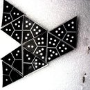
The construction of a prism refractometer is relatively simple. The prism cell can be made from 25 mm square pieces of glass microscope slide which are cemented together at the edges and mounted on another slide. Silicone sealant is suitable for use with most liquids, but other sealants can be used provided that they are inert to the test liquid. To ensure that the angles of the cell are as near as possible to 60 degrees, an equilateral triangular template can be made from stiff card and the cell assembled around it, using long modelling pins to hold the sides in place while the sealant cures. Care needs to be taken to keep the sealant confined to the joint surfaces only. If any is accidentally smeared on the faces of the cell, it can be carefully removed with a razor blade after curing. The stages of the construction of a prism cell are shown in Fig 2..
Step 2: Rotating Table


Once the cell has been made, it needs to be mounted on a rotating table. An easy means of doing this is to obtain the base section of a blank CD-R container and one of the clear plastic spacers which came in the CD pack. The central spindle is cut off about 2.5 mm above the base and the clear spacer disc is slipped over this short axle. The slide with the glass prism is then fixed to the spacer disc with double sided foam tape, so that it just clears the central spindle. The prism cell should then rotate freely about the spindle when the plastic spacer is turned. If the spindle is too high, file a small amount off until the prism cell and slide do not touch it.[See Fig 3 ]
Next you will need some rigid clear acrylic packaging material approximately 0.5 mm in thickness. From this, the index arm is cut using the pattern in Fig 4. ( If the CD container you have is different, you may have to make some alterations to the pattern. ) The vertical indicator card can be glued to a short “L” section as illustrated above.
Another vertical index tab is required for the zero mark of the refractometer. This can be made in the same way as the moveable index arm, but it does not need the central ring as it will be fixed in position. A pattern for this part is shown in Fig 5 above.
Step 3: Protractor Scale

A protractor scale now needs to be made, which is placed underneath the index arm and the clear disc holding the prism, and glued to the base of the CD-R container. A photocopy of a 360 degree protractor was used in the example illustrated, but only one quadrant of the scale is actually needed. It is a good idea to clear laminate the protractor scale if you can, this will preserve the markings indefinitely. A 40 mm diameter hole is cut in the centre to fit over the base of the CD-R container. The zero index tab is glued in position to coincide with the zero mark on the protractor scale. Ensure that the vertical index line is exactly aligned with the centre of the protractor and the zero degree mark.. The index arm is placed on top of the protractor scale and underneath the clear spacer disc carrying the prism cell. It should rotate freely without causing the spacer disc to move with it. The complete rotating table assembly is attached to a MDF base board. The components are assembled as shown in Fig 6.
Step 4: Laser Pointer

The next step is to mount the laser pointer ( only a 1 mW pointer should be used – lasers are dangerous to your vision ) so that the beam passes exactly above the centre of the rotating table, and is aligned on the vertical mark of the zero index tab. A 75 mm length of rigid PVC tubing and an aluminium bracket is used to mount the pointer on the base board. The height of the laser pointer must be such that the laser beam passes through the central section of the prism on the rotating table. The tube is drilled with two sets of 3 small holes spaced at 120 degrees to take the machine thread screws, which will hold the laser pointer in position. The screws should be a tight fit in the holes, so that they cut a thread into the PVC when they are inserted. Another hole is drilled above the pushbutton switch and a screw is inserted in this so that the laser beam can be turned on or off by turning the screw. The position of the pointer is then adjusted with the screws to align the beam with the zero mark. Be careful to protect your eyes from the laser beam when it is switched on. Fig 7 shows the completed refractometer in use.
Step 5: RI Measurement

Once everything is correctly aligned, the prism can be filled with the test liquid, using a pasteur pipette. About 5 ml of sample is required. If the liquid is volatile, place a 25 mm square of microscope slide glass on top to retard evaporation. The prism and the clear plastic disc are then carefully rotated until a position is found where the deviation angle of the laser beam has a minimum value. A magnifying lens will be found useful here to read the angle off the protractor scale, again taking care not to look into the laser beam. It is a good idea to switch off the laser while you are inspecting the protractor scale. The prism should then be rotated by 120 degrees so that the next corner is at the apex, and the minimum angle reading taken for each apex. If your prism has been accurately made with 60 degree angles, you should obtain the same minimum deviation angle for each of the 3 vertices of the prism. If they are slightly different, then just use the average value of the 3 readings, this will not introduce any significant error.. The average value of d is substituted into the formula RI = 2 sin ½ ( d + 60 ) to calculate the refractive index, or the RI value can be read from the graph above.
Step 6: Appendix a : Sources of Error in R.I Measurements


Some comparisons were made between R.I measurements made on this apparatus and a laboratory grade Abbe refractometer reading to +/- 0.0002. The results are tabulated above :
As can be seen, the average error is about 0.5 % . This would be adequate for most amateur microscopy purposes. The sources of error can be identified in three main categories :
1 : Measurement of the Minimum Deviation Angle
The protractor scale can only be read to +/- 0.5 degrees, which corresponds to an uncertainty of around +/- 0.005 in the refractive index value. The accuracy of the angle measurement could be improved by projecting the laser beam at right angles onto a wall at a distance of a few metres and measuring the minimum lateral displacement of the beam in the horizontal plane. ( see above )
The minimum deviation angle can then be calculated as d = arctan ( h / l ), where h = lateral displacement and l = distance from the centre of the prism cell to the wall. Assuming l = 2000 mm and d = 30 degrees, and thus h = 1155 mm, with the laser pointer that I used, the diameter of the laser beam spot on the wall is about 3 mm. This corresponds to an uncertainty in d of about 1.5 arc minute, or +/- 0.0003 in the refractive index value, which is approaching the accuracy of laboratory instruments.
2 : Wavelength and Temperature Errors
Refractive Index decreases with increasing wavelength of the light source. The standard wavelength for R.I measurements is 589.3 nm, the wavelength of the sodium D line, whereas cheap red laser pointers produce a wavelength of 670 nm. For most organic liquids, this probably introduces an error of about 0.002 in the R.I value, the value at the Na D line being higher. If you can obtain a yellow-orange laser pointer, this will give more accurate results, as these lasers have a wavelength of 583 nm.
Similarly, the R.I decreases with increasing temperature, for most substances this amounts to about – 0.0003 per degree Celsius. For optimum accuracy, the temperature of the sample needs to be controlled.
3 : Dimensional Irregularities in the Prism Cell
Variations in the thickness and perpendicularity of the glass walls and the prism angles will cause errors in the R.I values obtained. A difference of +/- 5 degrees from the correct prism angles of 60 degrees will produce an error of about +/- 0.001 in the R.I value determined by averaging the three d values. Hollow glass and plastic prisms can be obtained from commercial scientific equipment suppliers, and these are probably more accurate than home made prisms.
Calibration of the Refractometer with Distilled Water
The best method of checking the refractometer's accuracy is to measure the R.I of a sample of distilled ( or deionised ) water. At 670 nm and 20 degrees Celsius, the refractive index of water is 1.3317.
Step 7: Appendix B : R.I Value of Mixtures

In microscopy, it is often required to produce a series of liquids having known R.I values. It is only necessary to obtain two liquids having known R.I values which span the range of interest, and a series of intermediate R.I values can be matched by blending the two components. To a fairly good approximation, the R.I value of a mixture will be proportional to the volume concentration of the two components., providing the two liquids do not interact to produce significant volume dilation or contraction. Thus, given liquid A with R.I = a, and liquid B with R.I = b, the predicted R.I value of any mixture is given by R.I = Aa + Bb, where A = volume fraction of liquid A and B = volume fraction of liquid B. ( Note also that B = 1- A ). The graph above shows this relationship.

Participated in the
STEM Contest


