

Introduction: Line Follower Robot for Teaching Control Algorithms


I designed this line follower robot a few years ago when I was a robotics teacher. The objective for this project was to teach my students how to code a line following robot for a competition and also compare between If/Else and PID control. And not least, how the mechanics and the length of the robot affects this control algorithms. The goal was making it faster and reliable.
I made it to be programmed with the Arduino IDE, but is also possible to use the development IDE that you prefer. It has a powerful PIC32 with an USB bootloader, so you don't need a programmer. It also has an ON/OFF switch, a reset and a start/program button. The LEDs are connected to the motors PWM signal, so you can see the power that you are applying easily.
The robot is completely modular for experimenting and easy to repair in case that you have an accident with it. That makes this robot the perfect tool for learning programming in a very fun way. My students had used it for a long period and learned something new every time, even PID control. Not to mention that the sensor bar uses an algorithm to return an integer, negative value the robot is at the left, positive at the right and cero is on the center of the line.
Supplies
2x 6V Micro metal gearmotors with extended support brackets (Any gear ratio is ok, mine are 10:1)
1x Line Sensor board
1x Main control unit
1x 20 via flat wire, 1mm spacing. Mine is 20 cm long.
1x Acrylic linker (cut in 3mm clear acrylic)
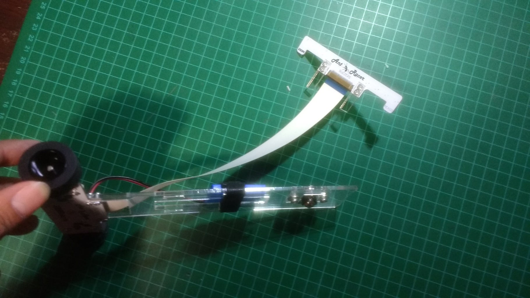
1x 1/8 caster ball (mine is metal)
2x Rubber wheel, 3 cm diameter.
1x Lipo battery. You can power the robot up to 10v, but keep in mind that the motors are rated for 6v.
Some M2 screws and nuts for attach everything together.
If you wish to make your own the design files, schematics and everything to build it are attached on next step.
Step 1: The Hardware


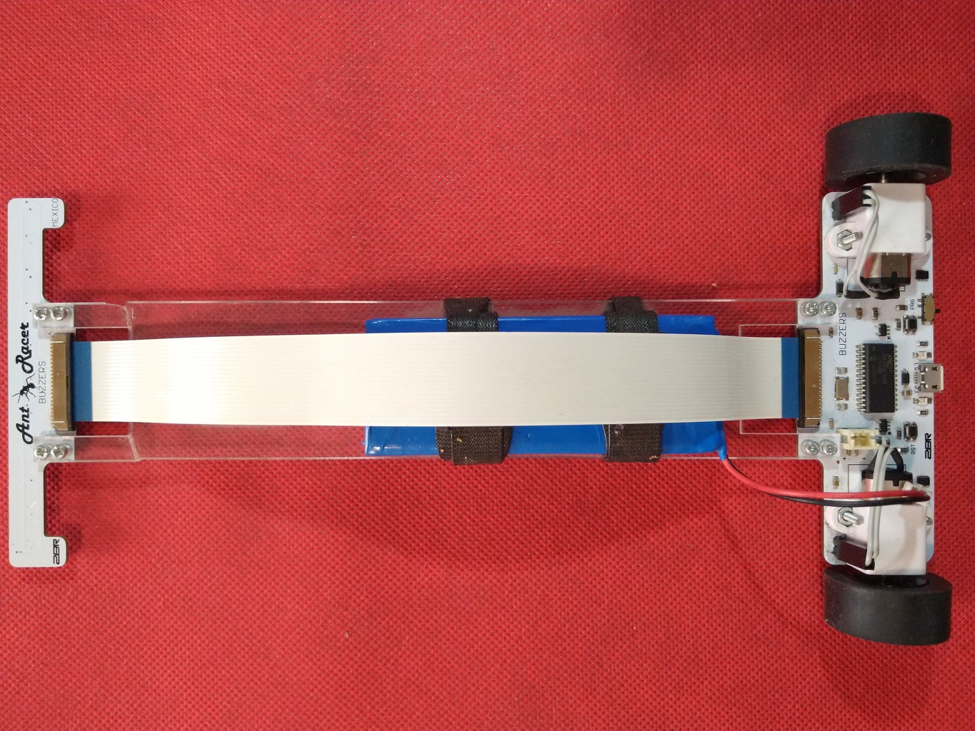
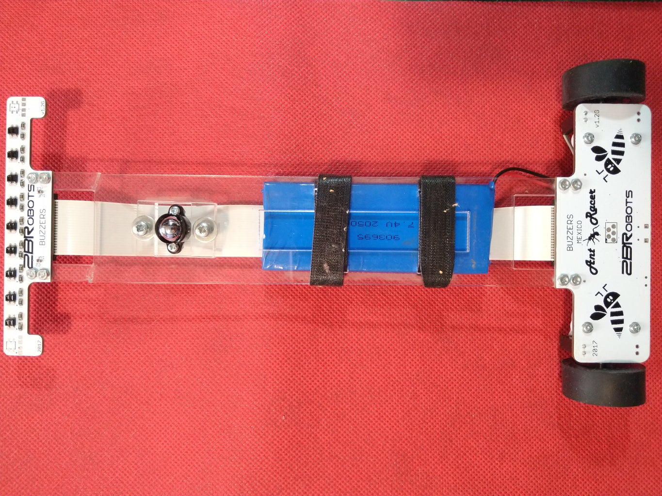
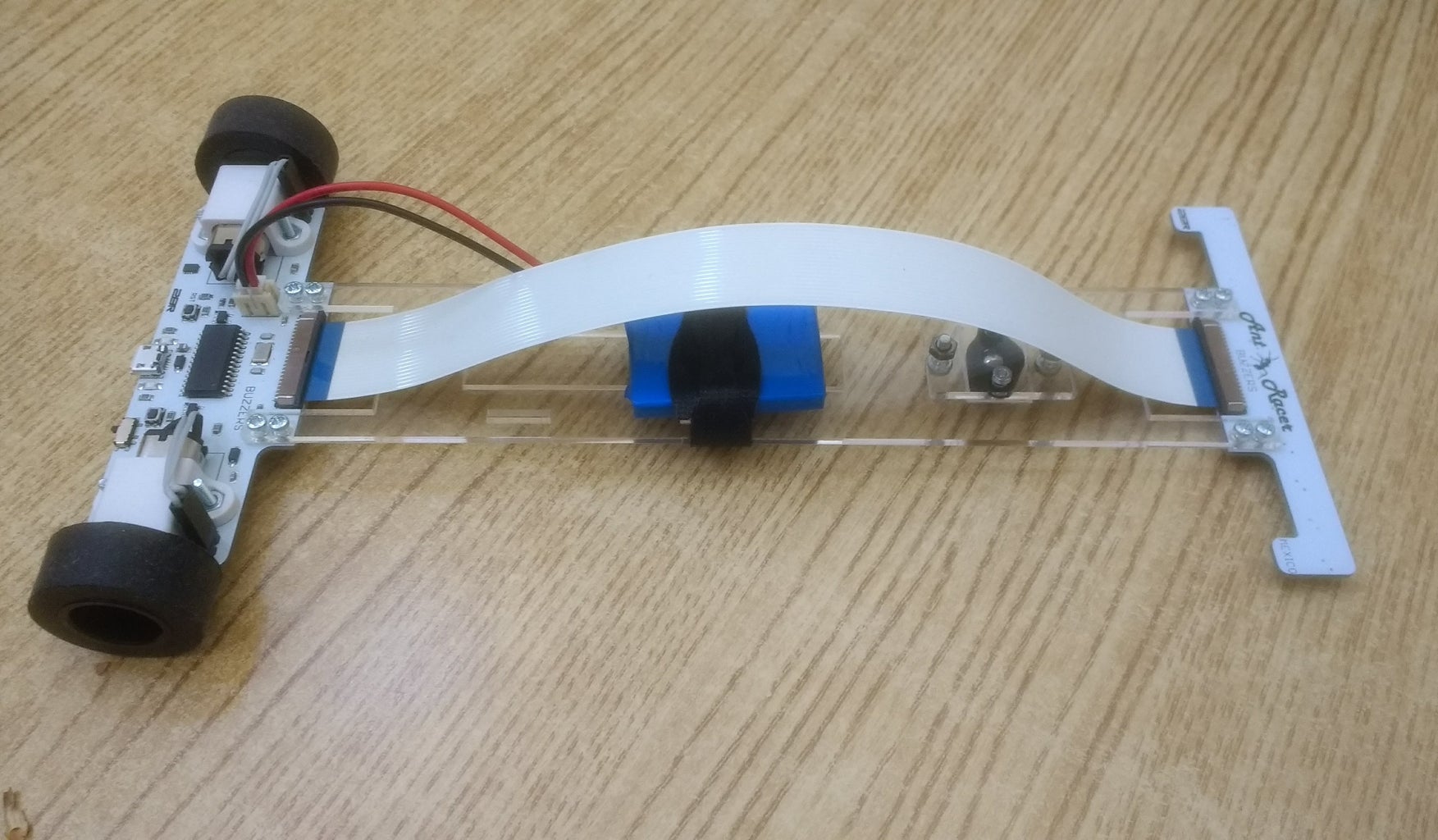
As you can see in the pictures all the component are SMD, is the perfect opportunity to practice your soldering skills. This robot was soldered by 3 of my students, so you can do it without trouble. All the design files are attached, you can see the files with EAGLE. Gerbers are also included if you want to the boards to your favorite PCB manufacturer.
The two boards are joined together with an acrylic piece, the laser cut pattern is included too. I used M2 screws and nuts for keep it in place. The ball caster is also placed in here. And if you crash the robot the acrylic will break and protect the boards from damage, ideal for testing! The flat wire is used to do the connection between the CPU and the sensor board. The motors are easily connected with wires to the CPU board.
Note: the PIC uses a custom firmware, is a modified version of the DP32 original firmware. You can get the firmware here. An ICSP connection is included on the bottom of the CPU board.

Step 2: The Software


I recommend to use the Arduino IDE to program the robot. As I told you before this line follower is based on the PIC32MX250 and it makes it compatible with the chipKIT DP32. You only need to install the chipKIT package on the package manager on the Arduino IDE and you are ready to go. Also you can program it on MPLAB or the IDE you wish, but you can learn the basis on Arduino.
The rest is like programming any other Arduino board. Plug the robot to your computer with a micro USB cable and press the program button immediately after pressing reset. Then send the sketch with the upload button in the IDE.
I have included 3 sketches on this tutorial. The first one test the sensor array, the second one is an If/Else line follower and the last one is a PID line follower. Everything is already working, however you will need to adjust some values if you change the design. And also feel free to do your own! There are better ways to do the line follower algorithm, experimentation is the key of success.
Attachments
Step 3: Experimenting

This is really the most important part, you should try all the possibilities and find the one that works for you.
Feel free to experiment with different diameter wheels and materials. Change the length of the robot modifying the acrylic joint. Use another battery, even with a different voltage. It can also be smaller or bigger. Maybe another gear ratio for the motors.
Modify the software to use less sensors or even try another algorithms, you can be surprised how much the performance can change. Or why not, if you are an advanced user do it with MPLAB.
The sky is the limit!
As an additional tip... Tuning the PID gains is a fascinating journey in which you can learn the effects on the robot when following the line with different values of Kp, Kd and Ki. Hours and hours of learning guaranteed!!! The kids will not notice that they are actually using math to perform all the tasks required.
I hope you enjoy this instructable, if you need something ask me in the comments.
Thanks for reading :)
Participated in the
Robotics Contest


