

Introduction: Make Your Own Microphone!


Intro
For a while now my audio has been less than satisfactory, so I decided to do something about it. And this is the result of that. It uses cheap parts and requires very little skill to make. I have put together a video for how to make it which you can watch at the top of the page. or you can click here.
Step 1: Making the Microphone
Before you build this we need to get a few parts together
For the parts list click here (includes everything you need apart from the tools and batteries (2X AA))
Lets get started!
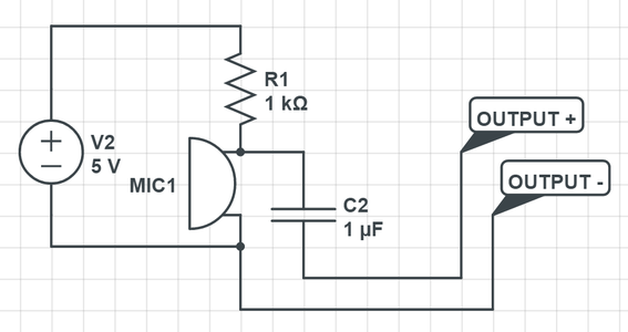
First lets take a look at our schematic (above).
Now the first thing that I will talk about is the power supply, (the symbol on the left) for that we will use a 2X AA battery holder (all parts listed in parts list above). Now if you don't know anything about reading electrical schematics then I would recommend watching the playlist of videos below made by one of my favorite YouTubers GreatScott!.
Tutorial videos to help you along can be found here and here
Step One:
The first first thing that you need to do is cut a 230mm length of rg402 coax (alternatively you could use wire) strip 7mm off one end and 10mm of the other leaving the inner conductor exposed.
Step Two:
Solder the electret microphone component to the 230mm length of rg402 coax (7mm stripped end). Positive on the center conductor and negative to the outside of the coax. Then insulate the connection with a piece of 4mm heat shrink tubing. You can then solder the coax to the board, the outside of the coax connects to one strip of your board and positive to the other (watch video for a better understanding).
Step Three:
Shorten the leads of the battery holder and strip the ends. Solder the negative wire to the negative board strip (outside of the coax strip). And solder the positive to a strip NEXT to the positive strip of the coax.
Step Four:
Solder the 1K Ohm resistor between the positive wire of the battery pack and the coax positive.
Step Five:
Solder the 1uF capacitor to the microphone end of the resistor and a separate strip on the board .
Step Six:
Solder the two signal outputs (not the ground pin) of the 3.5mm headphone jack together (otherwise you will have a mono stereo signal (sound on one side of your headphones)). After that solder wires to the connected signal output pins and the ground of the 3.5mm headphone jack, solder the other end of the signal wire to the capacitor (not the resistor end) and the ground wire to the boards negative.
Done!
Step 2: Conclusion
Building this microphone was very simple, it produces decent audio quality for the price and doesn't require a lot of skills to make.
If I was to do this next time I would have used a proper enclosure for the base of the microphone. I would also investigate using power from the computer (for example usb 5v power) but I ruled that out for this project because power from computers often have a lot of electrical noise, making our mic sound like static.
Thanks for reading!


