

Introduction: Math Learning for Kids With ESP8266


This project is a progress of my previous prototype made with Arduino Nano. The user is presented with a math problem, addition or multiplication, which he solves by typing with the keyboard. The device shows a cumulative counting of his right and wrong answers.
This time I wanted it to be an IoT device with a proper case, a battery and a decent look. That's why I replaced the OLED display with a Nokia 5110 LCD which has a metal bezel.
Step 1: Hardware
The required parts for the project are:
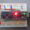
- ESP8266 board. I used Nodemcu for prototyping and a Wemos D1 mini for the final product because it is small.
- PCF8574T I2C Expander for the keyboard, to save pins on the ESP8266 board.
- 4x4 membrane keyboard module.
- Nokia 5110 display.
- Li-ion 18650 battery.
- TP4056 battery charger board.
- On/off switch.
- 30 AWG wires for the digital signals and 24 AWG wires for the power.
- A case 100x60x25.
The case should be long enough to fit the keyboard and screen. I couldn't find a smaller keyboard (even the 4x3 keyboard has the same footprint, it just has wider blank areas around the keys). But you can always use a touch display and get rid of the keyboard. I did want the nice click feeling.
I had a problem with the Nokia 5110 display after I fit it into the case: the display started to fade but it was visible from certain angles. I found out that the metal case distorted when I forced it into the hole of the plastic case. I removed the metal case and discovered that the LCD is connected to the PCB with a zebra connector, it is not soldered. When the metal case distorted, the LCD lost contact. There were also two small silicone studs on the back of the LCD that prevented it from getting good contact, so I removed them. I also put fresh solder on the traces that the zebra connector presses against. After that, the screen worked fine.
Step 2: Wiring

I used the hardware SPI bus of the ESP8266, and the hardware I2C bus. I believe it is more efficient than using the software bus. That's why I modified the Nokia 5110 example and moved some wires that were connected to the I2C bus.
- Nodemcu 3.3V, Nokia 5110 Vcc
- Nodemcu D5 (GPIO 14), Nokia 5110 CLK, Output from ESP SPI clock
- Nodemcu D7 (GPIO 13), Nokia 5110 DIN, Output from ESP SPI MOSI to display data input
- Nodemcu D6 (GPIO 12), Nokia 5110 D/C, Output from display data/command to ESP
- Nodemcu D0 (GPIO16), Nokia 5110 CS Output from ESP to chip select/enable display
- Nodemcu D4 (GPIO2), Nokia 5110 RST Output from ESP to reset display
- Nodemcu 3.3V, Nokia 5110 Baklight 3.3V
- Nodemcu D1 (GPIO 05), I2C Expander SCL
- Nodemcu D2 (GPIO 04), I2C Expander SDA
I set the I2C expander to address 0x20. If you don't know the address of your device, run a simple I2C scanner program.
Step 3: Software

The code is available on github: KidMathGameESP8266.
The code is based on my previous project with some differences, to port it to the new hardware.
I also included an OTA update feature. The OTA is activated when the "*" key is pressed, so that the device doesn't hang on startup waiting for your home network. The IP is displayed on a successful connection and it also has a timeout feature.
Another feature is setting the LCD contrast level with B and C buttons (up and down respectively). The nice thing is that the desired level is saved in flash and read back on the next startup so you don't need to set it each time.
Step 4: Conclusions
The device is connected to the internet, so basically you can show any information on the display. I used it as a fun math game for kids. It can be expanded endlessly.
I still didn't add any power saving features like low power mode of the ESP8266, or controlling the backlight with a transistor and a even a brightness control with PWM.


