

Introduction: Mobile Robot With PLC Control


I wanted to use this project to show how robots are controlled in industry and use it to demonstrate how PLC's are used instead of microcontrollers to control industrial machines such as robots. I decided to take a project, such as a line follower mobile robot, that would normally use a microcontroller and use a PLC instead so that the principles of industrial control can be explored in a friendly and familiar learning environment.
I will go through the mechanical construction and assembly of the robot together with the electrical and electronic engineering involved and then finally demonstrate how the PLC code works.
Why use a PLC? Programmable Logic Controllers (PLC's) are often used for controlling robots in industrial automation applications. PLCs can be programmed to manage and coordinate the movements and tasks of robots on the factory floor. They are the brain of the robot and are the central controller that processes inputs from various sensors and switches and sends commands to the robot's actuators and motors. The flexibility and real-time capabilities of PLC's make them suitable for adapting to different robotic tasks, improving precision, and enhancing overall automation efficiency in manufacturing environments. PLC's are used instead of microcontrollers in industrial robots for several reasons but here are the six main reasons:
- Robustness and Reliability: PLCs are designed to operate in harsh industrial environments. They are built to withstand electrical noise, temperature variations, and other challenging conditions, making them more reliable for continuous operation in industrial settings compared to many general-purpose microcontrollers.
- Scalability: PLCs are often used in large-scale industrial processes where there is a need for multiple I/O points and complex control logic. They can easily scale to accommodate a high number of inputs and outputs, making them suitable for controlling entire production lines.
- Specialized Functionality: PLCs come with built-in features tailored for industrial automation, such as communication protocols, high-speed counters, and timers. This specialized functionality simplifies programming for common industrial control tasks.
- Quick and Easy Programming: PLCs use ladder logic or other graphical programming languages that are intuitive for control engineers and maintenance technicians. This ease of programming allows for quick modifications and troubleshooting in industrial environments.
- Standardization: PLCs often follow industry standards, making them interchangeable and compatible with various devices and equipment from different manufacturers. This standardization simplifies maintenance and replacement.
- Dedicated Industrial Communication: PLCs support communication protocols commonly used in industrial automation, such as Modbus or Profibus (similar to CAN bus used in cars). This facilitates seamless integration with other industrial devices and systems.
The video in this section shows the mobile robot in action and the following sections show what was involved in building the robot and its operating environment.
Supplies


Here's a list of materials and tools I used to build the mobile robot.
Main Robot Materials
- Siemens LOGO 12/24V PLC
- Siemens LOGO 12/24V PLC I/O Expansion Module
- Upper Chassis 3mm plywood laser cut
- Lower Chassis 3mm clear acrylic
- Chassis Supports x 4 3D Printed PLA
- Robot Wheels & Gearmotor x 4 (available on Ebay and Amazon)
- Cargo bed 3mm plywood laser cut
- 12V Solenoid (I got mine from the pi hut)
- Solenoid bracket 3D Printed PLA
- Infrared sensors x 2 (Available from CPC Farnell DFROBOT)
- Ultrasonic sensor HC-SR04
- PWM Motor Speed Adjustment Module (Ebay)
- Magnetic Reed Switch
- Magnets
- 12V Relay Modules x 2
- Start / Stop buttons Spring Return x 2 (not shown in picture)
- Hook-up Wire (I used 22 AWG)
- Electrical Terminals - I used Wago's
- Solder
- 3.5mm screws x 4
- 4mm screws and nuts x 2
Tools and Equipment
- Laptop
- Fusion 360 Design Software
- Tinkercad design software
- Siemens SoftComfort PLC Software
- Soldering Iron
- Wire Cutters / strippers
- Ethernet programming cable (for PLC)
- Laser Cutter
- 3D Printer
If you want to build the Ultrasonic sensor to 0-10 / 4-20mA conversion PCB you will need:
- LM358 Dual Op AmpLow-power dual operational amplifier.
- Arduino Nano
- 1K OHM 0.25W Resistor x 6
- 100nF Capacitor Ceramic
- 4.7 uF Capacitor Electrolytic
- 500 OHM Trimmer Potentiometer to Calibrate 4-20mA Signal
- 15 Way Female PCB Header Pins to attach Arduino Nano
- 8 PIN IC Socket for 8-Pin Op Amp
- 4-Way PCB Screw Terminals for Output Signals
- 3-Way PCB Screw Terminals for Input from 10K Potentiometer
- 8 x 12cm Prototyping Board
- 26 AWG Hook-Up Wire, I used Red, Black, Yellow & Green
For the PCB that controls the Ping Pong Ball Depositor I used Tinkercad for the design. Tinkercad automatically generated the Bill of Materials which is included in section 3.
Step 1: Movement and Steering


This mobile robot, like many other microcontroller controlled mobile robots, is steered using the skid steering method. All though this is nothing new I have had to make some changes because using a PLC instead to a microcontroller and associated motor shield means I don't have these easy to use facilities to use.
Skid steering is a method of vehicle control where wheels on one side of the vehicle move independently of the other side. Skid steering involves applying different directions to the wheels on each side, causing the vehicle to rotate about its axis. Here are the 5 modes of operation:
- All 4 wheels of the robot are driven clockwise the mobile robot moves forward.
- All 4 wheels of the robot are driven anti-clockwise the mobile robot moves backwards.
- The right-hand side wheels are driven clockwise and the left-hand wheels are driven anti-clockwise. The robot turns right.
- The left-hand side wheels are driven clockwise and the right-hand wheels are driven anti-clockwise. The robot turns right.
- All wheels are told to stop. The robot stops.
The speed of the wheel motors is controlled by a PWM controller where by the operator sets a fixed speed to the motors. All the motors are driven by the same PWM controller to ensure they are turning at the same speed. PWM (Pulse Width Modulation) speed control involves varying the average power delivered to a motor by rapidly switching the power on and off. The width of each pulse determines the effective power sent to the motor. Increasing the pulse width increases motor speed, while reducing it decreases speed. PWM control is a precise and energy-efficient speed regulation for DC motors and is commonly used in industry for control of robots and conveyors.
The robot is able to follow the black line by the use of infrared (IR) sensors. IR sensors are made up of 2 parts, a transmitter and a receiver. The transmitter is an Infrared LED (not visible to the human eye), which produces the signal. The IR receiver senses the signal produced by the transmitter. When the sensor is over a reflective material light light is detected by the receiver and the sensor hives a high signal (5V). When the sensor is over the black tape the light gets absorbed thus giving a low output. The 4 conditions that the PLC enables are as follows:
- When both sensors are over a reflective material. All wheels move forward.
- The left sensor is over the black tape and the right sensor is over a reflective material. The robot turns right.
- The right sensor is over the black tape and the left sensor is over a reflective material. The robot turns left.
- Both sensors are over a non-reflective material. The robot stops.
The sensors I have used are powered by 5V and give a high output of 5V and a low output of 0V. The problem I have is that the industrial PLC requires a value of greater than 8VDC for a high signal and below 5VDC for a low signal. I have shown this in the datasheet attached. To overcome this I have used a transistor as a switch and the IR sensor switches the transistor. In this case I get a high signal of just over 11VDC and a low signal of 0VDC. I have attached a schematic of the design together with a simulation I have done on Tinkercad to show the transistor as a switch. The video of the Tinkercad simulation explains clearly how the signal from the sensors is amplified.
Step 2: Robot Safety


Wherever a robot is deployed it is critically important that the robot is safe so that it does not cause harm to other people or animals in the vicinity of the robot. It should also not harm the buildings or structures around the robot. For this reason industrial robots are designed with safety in mind. Industrial robots are often placed in safety cages so others cannot enter the operating zone. Mobile robots, as in this project, move around so they need to be equipped with sensors to warn people that the robot is near them and also the robot will come to a halt if a person or animal comes too close to the robot.
This mobile robot is equipped with an ultrasonic distance sensor to detect if anyone gets in the way of the robot. If a person, animal or object comes close the PLC activates a flashing light and sounder but keeps moving. If however the person, animal or object continues to get closer then the robot will stop and not move until the obstruction has moved.
I am using the analogue signal for this function. Ultrasonic sensors used in industry usually output 0-10V or 4-20mA and can be directly fed into the PLC. These sensors are often very expensive and are not appropriate for this project. Instead I am using a cheap HC-SR04 ultrasonic sensor and converting the signal from it to 0-10VDC using and Arduino and Op Amp.
The The Arduino outputs a PWM signal depending on the distance the object is from the ultrasonic sensor. I have averaged a running total of 5 readings from the HC-SR04 ultrasonic sensor to give a smoother output. A capacitor and resistor smooths out the PWM signal giving a 0-5VDC signal. This signal is then amplified to 0-10VDC by the OP Amp so that it can be used by the PLC. I have included a schematic of the PCB I built together with the Arduino sketch showing how the distance sensing is converted for use with the PLC.
Attachments

Step 3: Ping Pong Ball Depositor With Tinkercad


The Robot in this project is designed to do work in the same way that an industrial robot would in a factory, a farm, a hospital or any other situation you can think of. This robot is designed to collect ping pong balls from a location and deliver them to another location. This means the robot is part of a bigger system and when it gets to a set location on it's travels it enables another machine to deposit a ping pong ball into it's cargo hold.
A magnet in the track causes the robot to stop for a few seconds when the cargo hold is below the pin pong ball depositor. It also has a magnet on the robot that causes the pin pong ball depositor to operate and release one pin pong ball into the cargo hold.
The ping pong ball depositor uses two linear solenoid actuators in a tube of ping pong balls. When the sequence is called to operate the lower solenoid retracts and releases a pin pong ball. A second solenoid is mounted 40mm higher and is simultaneously called to extend which holds the other balls in place. After a set period of time (3 seconds) the lower solenoid returns to being extended and the upper solenoid retracts. This loads another ball ready for the next time it is called.
I decided to not use a microcontroller for this process it can be done simply with a 555 Timer IC working as an edge triggered monostable. An edge-triggered monostable 555 timer operates as a one-shot pulse generator. When triggered by a falling edge signal, it produces a single output pulse of fixed duration even if the input to the 555 is held low after the cycle is completed.
The way this circuit works is as that initially, the 555 timer's output is low. Upon trigger, the internal flip-flop sets, causing the output to go high. Simultaneously, the 555 internal discharge transistor is activated, and the timing capacitor charges through an external resistor. Once the capacitor voltage reaches a threshold, the flip-flop resets, driving the output low. The time the pulse is held high is determined by the resistor and capacitor values. Subsequent triggers during the pulse have no effect because the trigger is activated by draining a capacitor on the trigger pin on the 555 timer. However another resistor connected to positive voltage almost immediately makes the trigger pin to go high causing the edge triggering effect.
I used Tinkercad to design and simulate this circuit. This is the first time I have used Tinkercad and found it very easy to use. I have included a video of the design and a simulation of the circuit using the Tinkercad simulation mode. The great thing about Tinkercad is that it also automatically creates a Bill of Materials (BOM) and schematic design that I have attached.
I made a laser cut tube for holding the ping pong balls and mounted the tube using industrial channel 40mm x 40mm galvanised steel channel. This type of channel is commonly used in industry and often referred to as "unistrut" which is a trade name.
I used Fusion 360 to design the brackets that mount the two linear solenoid actuators and then used Fusion 360 to export the design to a .stl file which I could then 3D print.

Step 4: Electrical Design

PLC's are very easy to connect up compared to microcontrollers and don't require lots of fiddly soldering because they are designed to be installed, maintained and modified by electricians in factory environments. As such the electrical design is simply providing power to the PLC and ancillary PCB's and then connecting up all the inputs and outputs (I/O).
I have included a schematic diagram to show all the electrical connections. This type of diagram is very similar to what is used in industrial equipment.
The robot is powered by a single rechargeable sealed lead acid battery, often called a SLA battery. To distribute power to the PLC and and other equipment I used lever lock terminals, the brand I used was Wago. This made connection very easy as I could use each block do distribute power and ground. You just need to pull up the lever, insert the stripped wire and then snap the lever down. The wires connected to the block of 5 terminals are then all connected.
A tip for wiring the robot is to not make your wires too short as it is easier to neatly route longer wires. You can always shorten them when you are done. You can tidy up your wiring with cable ties but I wouldn't do this until after you have tested it in case you need to change anything.
Step 5: Mechanical Design and Assembly


I relied heavily on Autodesk Fusion 360 for the mechanical design of this mobile robot. I used it to design the robot chassis and also the brackets for the solenoids.
I've included a short video showing how I designed and assembled the robot assemble using Autodesk Fusion 360.
I made the chassis upright supports and solenoid brackets from from 3D printed PLA. To design the components I used Fusion 360, first creating a 2D sketch of the shape I want as 3D. I then extrude this shape. An object such as the bracket may be made up of several 3D shapes that move to the correct position of the completed object and then I use the combine button to join together. I was also able to use Fusion 360 to assemble the top chassis, bottom chassis and upright supports so that I could see how the robot chassis assembly looked.
Once I was happy with the 3D object I exported it to an STL File. Although you can output a Fusion 360 model directly to a 3D printing utility I tend to use Ultimaker Cura to slice my 3D prints as it is already setup with my 3D printer (Ender 3 Pro).
The robot top and bottom chassis were laser cut as was the ping pong ball depositor. I have included a .dxf file of these components that were laser cut. These files can be opened with most 2D software drawing packages such as AutoCAD LT or AutoCAD Web.
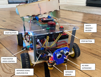
I have included an annotated photograph of the completed robot assembly with all the components annotated attached.
Attachments
Step 6: PLC Code

The PLC and associated Code is what makes this mobile robot unique. PLC's were originally designed to be easy to use and PLC programming is relatively simple and intuitive to use. I used Ladder Logic Programming for this project however there are several other programming methods you can use such as Structured Text (ST), Function Block Diagram (FBD), Instruction List (IL), Sequential Function Chart (SFC) and Structured Control Language (SCL). Nearly all the PLC's I come across in industrial Controls use LAD or FBD. I used Siemens Logo Soft Comfort Software to program the PLC as I have a licence for this software and enjoy using it. There are many free PLC software packages available however the majority of my clients have Siemens PLCs so I have my own licence. You can use the Siemens software for free which enables you to simulate your design but not upload it.
PLC ladder logic programming, LAD, is a type graphical language used to program PLCs. It shows logic operations using symbolic notation in ladder diagrams, resembling traditional relay circuits. Each rung of the ladder represents a logic operation. Ladder logic is mainly for bit logic operations (true or false), but it can also handle analogue inputs, which I use for object distance sensing on this robot. It’s a graphical language making it easier to learn, especially if you’re familiar with electrical circuits. LAD programming is like creating logic expressions for automation, similar to the rails and rungs of relay circuits.
I have done a video going through the PLC code for this robot. The graphical representation can be a bit confusing for people who are used to working with electronics schematics. This is because a normally open contact in LAD programming is two vertical bars which looks like a capacitor on a normal electronics schematic drawing. A normally closed contact is two vertical bars with a diagonal slash through it.
A PDF of the Ladder Logic is included.
Attachments
Step 7: Final Comments
This was quite an involved build but I hope you learned some things about PLC's and Industrial Controls.
Finally, I always name every robot I build and I've decided to call this one Indiana_Codes.
Second Prize in the
Robotics Contest


