

Introduction: Modifying a Variable Transformer With a Digital Power Meter and Other Add-ons


Needed a 10A variable AC supply that I could control from 0V to 140V AC for controlling 1000W heating elements. And had a beat up variable transformer, a PowerStat, that I had for 10+ years so time to bring this guy into the age of science and enlightenment! I converted one of those amazing little power meters to read from 0VAC instead of from 80VAC and added a 3D printed reduction knob to give finer control over the voltage. Plus an output fuse and an output switch.
Supplies

Most of the parts were from my parts drawer, harvested from old devices. The Powerstat device, two power switches, an AC socket, an IEC AC Input socket with built in fuse, a fuse holder, two banana plugs, the power meter, and my 3D printed knob plus some hardware, plywood and paint made up the list.
Step 1: Checking Out the Old Powerstat Variable Transformer


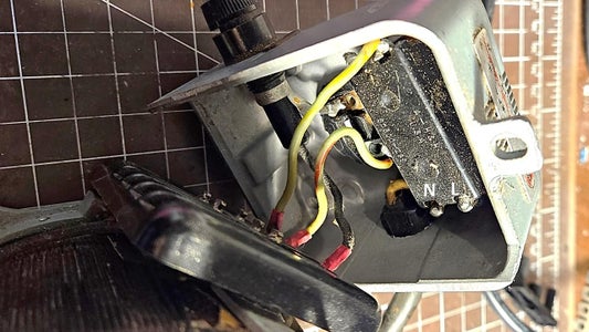


The Powerstat that I had for a decade plus looked pretty beat up with the knob having disappeared. Was not sure about the extent of damage, but an ohmmeter check showed that the wiper and coil were ok. It had a nice power switch and fuse holder but the AC outlet was a 2-pin socket with no earth connection. Could get the powerswitch out but damaged the fuse holder. The insides looked ok except for the expected dust. Took pictures of the wiring - just in case.
Step 2: Tracing the Old Circuit and Designing the New Circuit


The circuit of the variable transformer was traced before I disassembled the unit and it was pretty standard and is shown in the first diagram. The transformer input labeled 3 on the terminal block is the wiper, and 1 is neutral and 2 is live. To modify this I would feed the Live input AC power to terminal 2 of the transformer as well as the modified power meter. The wiper (3) goes to the Power Meter's live input, and Neutral is connected to the Neutral of the transformer as well as to the Power Meter's neutral input. The Live output from the power meter is connected in series to a fuse and a power switch and then to the live of an AC outlet and a banana socket. The Neutral output from the power meter is connected to the neutral of the AC outlet and a neutral banana socket.
I will describe the modifications of the power meter in the next section.
Step 3: Modifying the Power Meter to Read From 0VAC


The small power meter is a pretty incredible piece of engineering as in a small cheap device it gives you voltage, current, watts, power factor, energy used and AC frequency from 80VAC to 240VAC. Unfortunately, the meter can only be supplied with 60-80VAC minimum otherwise it turns-off. To read from 0VAC we need to make a simple modification. First step in the modification is to open up the back of the case by removing 4 small screws at the 4 corners. Then popping out the single PCB.
The power supply for the meter is derived from the AC trace that feeds the R15 resistor (and then that goes on to an AC to DC converter). WE break this AC trace (red line in 3rd figure) and connect a stable > 80C AV voltage to the input of the R15 resistor (shown as a green pad). That's it. The power meter now reads from 0 VAC.
Step 4: Making the Enclosure


I try to use 6 inch dimensions for my larger projects so played with the parts in trying to get them to fit in the 6 inch cube constraint. Once I had that figured out I designed the front panel to hold the switches, AC out, banana plugs, and the fuse holder plus a hole for the shaft that turns the wiper on the variable transformer. Then etched and cut the front and back panels out of 5mm plywood. The other sides of the enclosure were cut on a bandsaw. I glued or screwed the back, bottom and one side panel with the help of triangular pieces of wood so that the enclosure is strong enough to hold the heavy transformer. I painted the inside with gray flooring paint. The front panel got a coat of black paint followed by the etched letters filled in with white acrylic paint.
Step 5: Wiring


I did not take enough pictures of this step. Essentially, I followed the wiring diagram as shown here and in some of the pictures. The five wires that connect to the Power Meter
(i) AC Neutral from main power switch to Power Meter Neutral,
(ii) Transformer wiper screw terminal to Power Meter AC live in,
(iii) Transformer Live AC In screw terminal to Power Meter R15 resistor (white wire)
(iv) Power Meter Live AC Out (Load L) to Output Fuse
(v) Power Meter Neutral AC Out (Load N) to Output AC Socket.
were pulled out from the front opening and then connected to the Power Meter screw terminals.
The Power Meter was slid in and the set up was tested. No smoke, the meter came on.
Step 6: The 3D Printed Reduction Knob


One challenge with my design was that the knob to control the voltage was too close to the Power Meter display. It takes some effort to rotate the variable transformer wiper so a small knob did not work. I needed to relocate the position of the knob lower down and give it a bit of a mechanical advantage so the wiper would turn more easily. I designed a gear reduction device with the larger gear slipping over the transformer shaft and the smaller gear attached to a knob. I used the FreeCad Gears workbench to design a 1/3 reduction, that is three turns of the small gear (with the knob) will result in one turn of the transformer shaft, and this would require approx. 1/3rd the force. The two gears, and the casing for the gear were printed out of PLA on an Ender 2 Pro with 100% infill for the gears and 50% infill for the casing.
The big gear was slipped on to the transformer shaft, the fitting was tight enough that glue or a side screw were not needed. Then a hole was drilled in the front panel to take the shaft of the smaller gear. The shaft of the small gear was slipped into the hole. A bit of vaseline, and the casing was attached with 4 screws as shown in the last picture. And a regular potentiometer knob was attached to the small gear shaft with side screws.
Well, the knob worked really well except it changed the direction of the shaft. When I turned the knob to the right the voltage decreased instead of increasing. So had to rewire the transformer as shown in the next step.
Step 7: Final Assembly


To ensure that the direction of the knob corresponded to the change in voltage (clockwise = increase, anti-clockwise = decrease) I had to rewire the transformer as shown in the first picture. I shifted the Neutral wires from screw terminal 1 to screw terminal 4, and the Live wires from screw terminal 2 (second from bottom left) to screw terminal 5. That worked.
Step 8: Testing: From 0 VAC to 140 VAC


Turn, turn, turn to get from 0 VAC to the maximum 140VAC. From junk to something nice!


Participated in the
Fix It Contest


