

Introduction: Modular Automata


An automaton is a self-operating machine, or a machine or control mechanism designed to automatically follow a predetermined sequence of operations, or respond to predetermined instructions. (obtained from wikipedia)
As soon as I saw my very first automata I wanted to know how they work and if possible build my own. With this in mind, sometime ago I built a kit for 3D priting that allowed me to do that and called it simply Modular Automata.
This design consists on a set of independent boxes, each one able do execute a type of motion, linear along the x axis, linear along the z axis and rotational. You can print and combine several of these boxes and add signs to them for that extra bit of customization, finally you simply turn a small knob and that motion is transmitted through all boxes thus bringing your custom automata to life.
That project was designed in my software of choice at the time, Rhinoceros, but more recently I've been dabbling in Fusion 360 and this project seemed a perfect fit for Fusion 360 due to it's parametric nature, while I do like Rhino, it's a pain to change part of a design, that same task in Fusion 360 usually does not require much more than right-clicking on the feature and changing the required value.
So for this instructable, I will show how I converted my original design from Rhinoceros to Fusion 360.
Step 1: Original Data


I went back to my original files, trying to grasp what would be required and as I expected it wouldn't be a walk in the park. I divided the original design in two sections, the first one being the box where the mechanisms would reside and the second one the mechanism.
The images give an glimpse of what is ahead, but they also show what would be behind, before I was forced to create a mess of lines so that I could create the surfaces I needed and these were, for a lack of a better word, confusing.
So how to move this design to Fusion? Well I could simply export the design and then import it in Fusion but in this way I wouldn't gain much, to change anything on the design would still be a nightmare, what I really want is parametric design, why? Simple I want to be able to easily resize the design with minimal changes and most of all, quickly.
So let's begin, as I already tested this design and I know it works I will begin by obtaining dimensions from key places and I will use those to recreate the design, for this I used the Linear Dimension, and Aligned Dimension tools.
Some parts were a bit tricky to obtain mainly due to the fact that I no longer had the original lines nor did I remembered the exact steps I took to obtain that particular shape. For those I obtained lines from the edges that I then exported in dxf, followed by a import in Fusion 360.
Step 2: Boxes


Using all the measurements I obtained from Rhino, I started sketching, creating a similar design that I then constrained by placing the correct dimensions, so in a couple of minutes I already had all dimensions done, from here to the extrude and to the virtual assembly of the three boxes was a breeze and very rapidly the boxes were ready.
Notice that there are two different types of top covers for the boxes, one for the x linear motion and the other for the two other motions. So every complete box will need two covers for the top and bottom and then 4 side covers.
Step 3: Clips and Shafts


To transmit the motion a 3 mm shaft is used, you can also replace this with 3mm wooden skewers, it's a lot easier to assemble that way. Every shaft e connected to each other with a small collar and each cube is connect with a small two part clip, that joins the cubes and stops then from rotating. Once again, I obtained the dimensions from Rhino and then proceded to create construction planes and applying the shapes required to extrude de bodies that were required.
Step 4: X Motion


For the X motion, I used a grooved cam to provide a uniform reciprocating rectilinear motion (http://507movements.com/mm_106.html). This consists on a cylinder with a groove that drives a small sled on top of which the sign is placed.
On this particular part I exported the groove path to dxf and imported the dxf in Fusion 360 and proceeded to base my measurements from there. The cylinder consists on two parts that are joined together with a hex insert, this insured that both halves will rotate simultaneously. The sled rides on top of two tracks that is then forced in to staying in place by the top of cube, on the bottom of the sled there's a small pin that sits inside the cylinder groove. Both the sled and the tracks need to be smooth to ensure that the motion is also smooth, to help this you can add a bit of lubrication, I used a PTFE based lubricant and it works perfectly.
Step 5: Rotational Motion


For the rotation movement I used two gears that I generated in http://geargenerator.com, one of the gears sits on the main shaft and the other on top of a small holder. This setup transfers the rotating shaft movement 90 degrees thus allowing the motion to "escape" through the top of the cube.
After generating the gears, I imported them in Fusion and scaled them to the correct dimension and placement. Afterwards it was only necessary to build the holder and a small place where the sign would be placed.
Step 6: Z Motion


For the z linear motion, I went as simple as I could, a simple off center circle, on top of which a sign holder rides. While this setup works, I had to add a clip to increase the surface area of the holder and also small vertical pins to ensure that the motion would be linear and consistent. Don't forget to ensure that these pins are smooth and add a bit of lubricant to them.
Step 7: Crank


Finally the crank. It consists on three parts, the crank itself that clips on the main shaft, a small pin and a roller. Once again the original dimensions where obtained from Rhinoceros and simply applied in fusion with the dimension tool.
Step 8: Signs


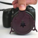
The signs are quite simple to make, the only real important piece is the shaft that will connect to the cubes, this shaft has a 3mm diameter. What you place on the automata is your choice. For mine I decided to build a small birthday gift, so I combined different sized letters (the font is Gilligans Island) and added the center shaft to both words "Happy" and "Birthday", for the ballons, I combined three ballons, and them built 3 inserts to place on top of the main sign, just to give a bit of color to them.
Step 9: Conclusion


This project was without a doubt one of the most complex I ever done, and surprisingly it works rather well as you can see in the video. Hopefully after the description I made you can now assemble it without too much trouble.
To further help with your build I provide the Fusion file "Modular Automata v22.f3d" and also a link for the public link to it, http://a360.co/2pUvkFa.
So, just to wrap up here are the simplified steps for this build:
1- Choose how many cubes you will need.
2- Create your own signs. Using Fusion create your sign and at the bottom of it add a cylinder with at least 2cm of height and with a diameter of 3mm.
3- Choose the mechanisms you will use (the sliding one requires a different top face for the cube).
4- Print all the parts required (stls.zip file)
5- If you have access to wooden 3mm chopsticks or skewers, use it instead of the axle provided, it's a lot easier to assemble.
PS As you assemble the cubes start adding small drops of glue, it avoids the assembly falling into pieces if you accidentally drop it. Also add a bit of lubricant (I use a PTFE based one) at key places to ensure a smooth motion.


Third Prize in the
Design Now: In Motion Contest


