Introduction: Multi-Layered Edge Lit Acrylic Sign With Color Changing Animations!
I've always seen people post edge lit acrylic sign projects and always wondered what a multi layered sign with individually addressable LEDs with multiple colors and animations going at once would look like!
Supplies
- Wood (for base)
-I used underlayment from Home Depot (cheap way to get nice looking 5mm plywood)
- 12" x 24" 1/8" acrylic sheet
- ESP32 W-ROOM
- ESP32 Developer Board (to connect power and LED's to ESP32)
-See link below to view both ESP32 and Developer Board I used
- 3d printed parts (self-printed or ordered)
- 1 meter WS2812-B or WS2512-IC individually addressable LED's
-144 pixels/m density (60 will also work it will just be dimmer and some animations won't be as smooth)
- 5v power cord to power Developer Board
Affiliate Links to Supplies
ESP32 & Developer Board:Amazon.com: AITRIP 2 Sets ESP-WROOM-32 ESP32 ESP-32S Type-C USB Development Board Type-C USB CH340C WiFi+Bluetooth Ultra-Low Power Dual Core ESP32-DevKitC-32 ESP-WROOM-32 Expansion Board for Arduino : Electronics
Step 1: Cutting Out the Base
- I made the base out of 5mm plywood I got at Home Depot in the flooring section. Its called underlayment and pretty darn cheap for how nice the veneer on the top looks.
- I then used BasedBox - Boxes (festi.info) to generate the .svg of the box. I have attached the .svg file I used which has the top hole for the acrylic and the back charging port hole.
- I used the same wood for the backboard that goes behind the last sheet of acrylic. (see step 2)
- I then cut out the box and backboard on a laser cutter.
-If you don't have a laser cutter you can make a box out of whatever you have around (foam board, Legos, etc.) The finger joints look nice but are not necessary. If you have to make the box, the only really important dimension is the rectangular hole in the top (27.75mm x 139mm). As long as that is the right size, the rest of the box can be any size. Just make sure it has enough room for the ESP32 and Developer Board plus the LEDs in it.
-(I decided to add a 3d printed base .stl so you can print the base too if you'd rather not build it.)
- Cut a hole in the backside of the box with the laser (I included both the center hole in the top where the acrylic goes and the square hole on the back for the power port.) (Can use a drill if no laser available.)
Step 2: Assembling the Base
- Glue all the sides of the base together other than the bottom, that will be done at the end.
-(If you printed your base its already a single piece and you can skip this bullet point.)
Optional Steps
- Use a router to round the edges.
- You can stain and finish or paint the box however you desire. I used 2 coats of teak oil and then 2 coats of polyurethane.
- I also used the laser to etch a groove on the inside of the box for the board to sit flush inside.
Step 3: Paint Backboard
Since the acrylic is clear, it needs some backing to help the colors pop when it is lit.
- I used the same wood as the box and cut out a rectangle (203mmx135mm) with the top corners rounded (16.5mm), this is same shape acrylic will be cut.
- I included the backboard as part of the .svg file in the previous step.
- Spray paint the ugly side of the backboard with black spray paint (matte works best to absorb the light) and cover the other side with the same stain or finish you used on the rest of the box.
-You can also cut out and glue black paper or felt to the board if you can't paint it.
Step 4: Print 3D Printed Parts
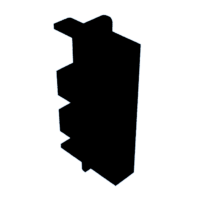
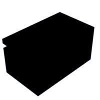
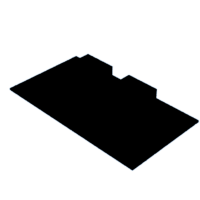
Now we are going to print all the pieces that hold everything together and in place. I have attached the files below. If you don't have a 3d printer you can always send the files to a print farm, and they will print them and ship them to you.
Attachments
Step 5: Wiring the LED's
- Take the ESP32 and press fit it into the corresponding holes on the Developer Board. The pins should line up on the ESP32 with the holes Developer Board. You might have to slightly bend the pins to fit them in the holes.
- Cut 3 strips of 18 LED's each.
- Place them in the 3d printed led strip holder. They should fit snug with the strips overlapping up to the acual LED.
- Solder the two power wires and the center data wire to each of the 3 strips. (9 total wires)
- Take the 3 positive wires and solder them to a single wire.
- Repeat with the 3 negative (ground) wires.
- Connect the other end of the positive and negative wires you just combined to the pins 5V and GND pins on the Developer Board.
- The 3 remaining wires should be the 3 center data wires.
- Connect them to the following pins on the Developer Board: D15, D16, D17.
- Use the column of pins closest to the numbers (S column).
Since each strips data line is now connected to a different pin on the board, we can use 3 different color animations, one per strip.
Step 6: Cut Out and Etch Acrylic
For this project I am using 3 layers of acrylic. I used 1/8" acrylic which almost perfectly is the same width of the leds.
- Cut out the 3 rectangles of acrylic, with the rounded top corners, (The same size of the backboard from step 3.)
- Find a picture online (sports team logo for example) or create one yourself that would look good with 3 colors.
- Edit the photo (if nessesary) to have 3 different colors using Photoshop or Gimp (free alternative).
- Split the colors of the picture into 3 different pictures so each color of the image is on its own piece of acrylic.
- Mirror the image so the etching will be on the back of the acrylic once installed in the base.
- Etch the designs into the acrylic, then cut out with a laser.
If No Laser Is Available
- Print your design out on copy paper then place it under the acrylic and use a Dremel to trace and etch in the design.
Step 7: Assembly
- Take your box base and snap in the led holder with the led strips already in it into the top hole in your base.
-(The longer groove goes towards the front.)
- Place the ESP32 in the box with the charging port facing the hole in the back.
- If there is extra space behind the board and it just pushes into the box when you try to plug it in I have attached a spacer piece that press fits between the board and the inside of the box in step 4 called "board to box spacer."
- Glue the printed acrylic holders on the sides of the top hole in the box.
-they should slide into the slots on the acrylic holders and be lined up to perfectly cover each row of LEDs.
- Glue the trim over the acrylic holders.
- Place the etched acrylic and the backboard in the printed acrylic holders and glue down.
- Place the two reflection blockers between the first and second acrylic and second and third acrylic. Push them to the bottom so they are covering the rest of exposed led strips. This reduces the internal reflection of the actual led pixels on the acrylic, so you only see the lit up etched part.
- Place the spacer on top the acrylic, properly spacing it out and place a drop of superglue on top.
- Place the big arch over the acrylic and press top into the glue on the spacer from the previous step and glue bottom to the trim (see arch in cover photo).
Step 8: Programming Your LEDs
The final step is to program the ESP32 board to run the LEDs with the colors and animations you want. For this we will be loading WLED to the board.
- I used this great tutorial. The part you want starts at 16:40. (The beginning of the video is making the Developer Board we bought.)
- If your board is being registered by your computer try plugging the usb cord directly to the esp32 port instead of the port on the Developer Board. Also make sure the usb is plugged directly into the computer as opposed to a usb port or adapter.
- First we need to go to Config, then LED Preferences.
- We need to set it up so there are 3 different led strips, to do this first fill out the following information,
START: 0
LENGHT: 18 (or however many you have per strip)
GPIO: 15
- Hit the plus button now to make your second strip.
START: 18
LENGHT: 18 (or however many you have per strip) (I had only 17 on this one, had to cut and resolder)
GPIO: 16
- Hit the plus button now to make your second strip.
START: 36
LENGTH: 18 (or however many you have per strip)
GPIO: 17
- Below this make sure you check make a segment for each output.
- Now comes the fun part. Go thru all the colors and animations and choose which you want for each segment.
YOUR ALL FINISHED. SIT BACK AND ENJOY YOUR CREATION!
**Bonus: You can access your esp board thru wifi and change the colors and animations thru the WLED phone app or your computer as long as its connected to the same wifi as the board.**

Participated in the
Anything Goes Contest


