

Introduction: My Ninth Project: Robot Arm With Joystick Shield


Although it is great controlling the robot arm with computer or mobile phone, I think using joystick is also cool, so I've bought a joystick shield and make a new project. This joystick shield is compatible with Arduino. It also support Nokia 5110 LCD module, nRF24L01 wireless module and Bluetooth module. It should be fun and convenient for various projects. : )
Step 1: Parts


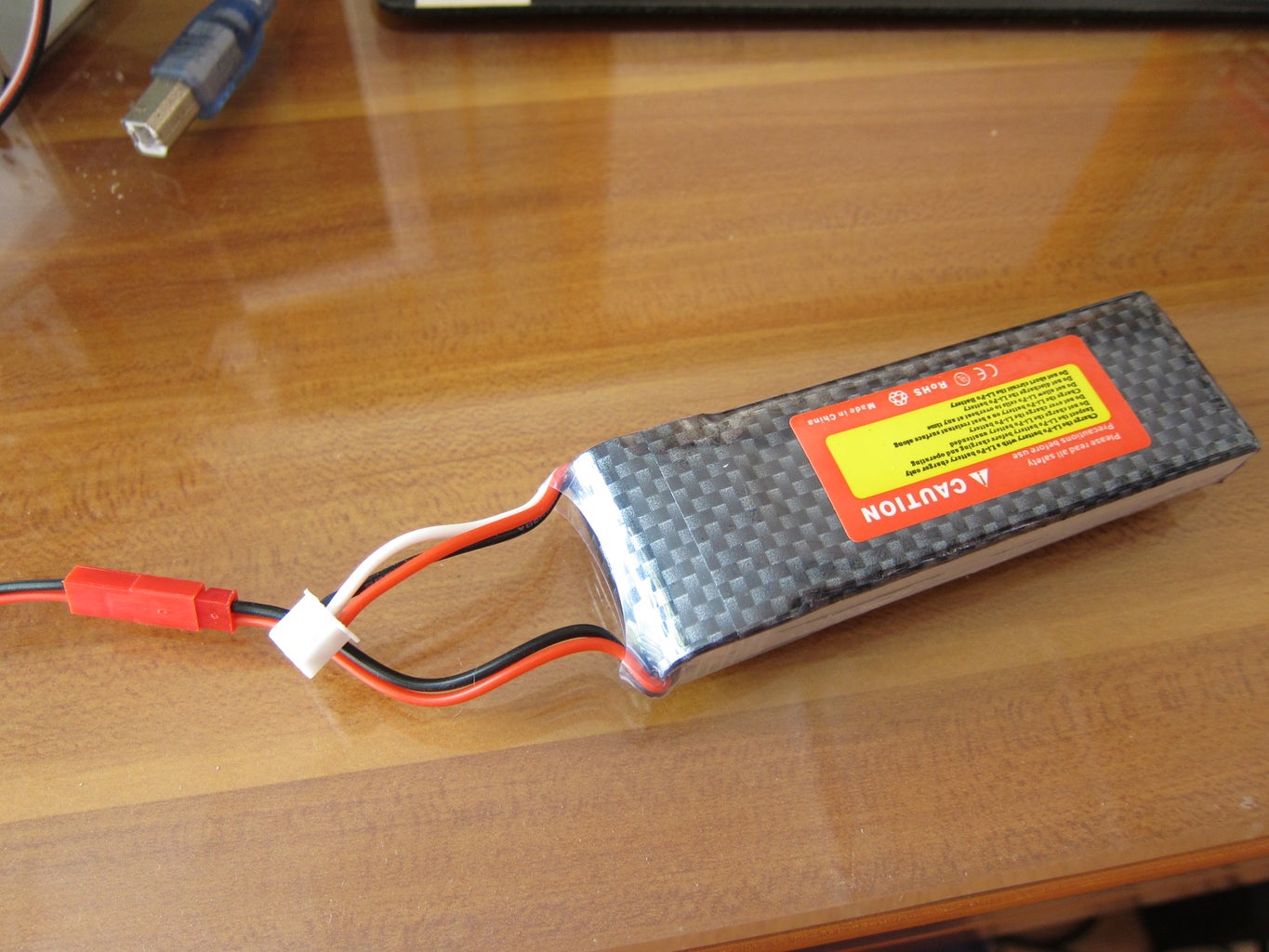
7.4V Li-Po Battery
Charger
JST female connector
Standoff
Step 2: Assembly

For assembling Robot Arm Set you can follow the manual downloaded from the link. You can also refer to my seventh project. For Joystick Shield it is very simple: There are pin headers that are compatible with Arduino, just plug this shield to the pins on Arduino UNO / MEGA and that's it.
Step 3: Wiring
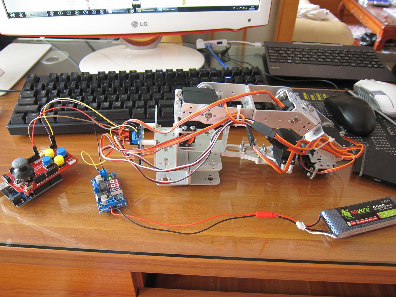

This is a continuation of the seventh project and the wiring between robot arm and servo controller is just the same.
For servo cable:
Brown = GND
Red = +
Orange = Signal
From servos to servo controller:
Servo at the base > S1
......
Servo at the claw > S6
Use extension wires if the servo cable is not long enough. Make sure all the cables are in correct direction.
For Battery:
Red wire of 7.4V Li-Po Battery > IN + of buck regulator
Black wire of 7.4V Li-Po Battery > IN - of buck regulator
For Buck Regulator
OUT + > VS of the blue terminal block on servo controller
OUT - > GND of the blue terminal block on servo controller
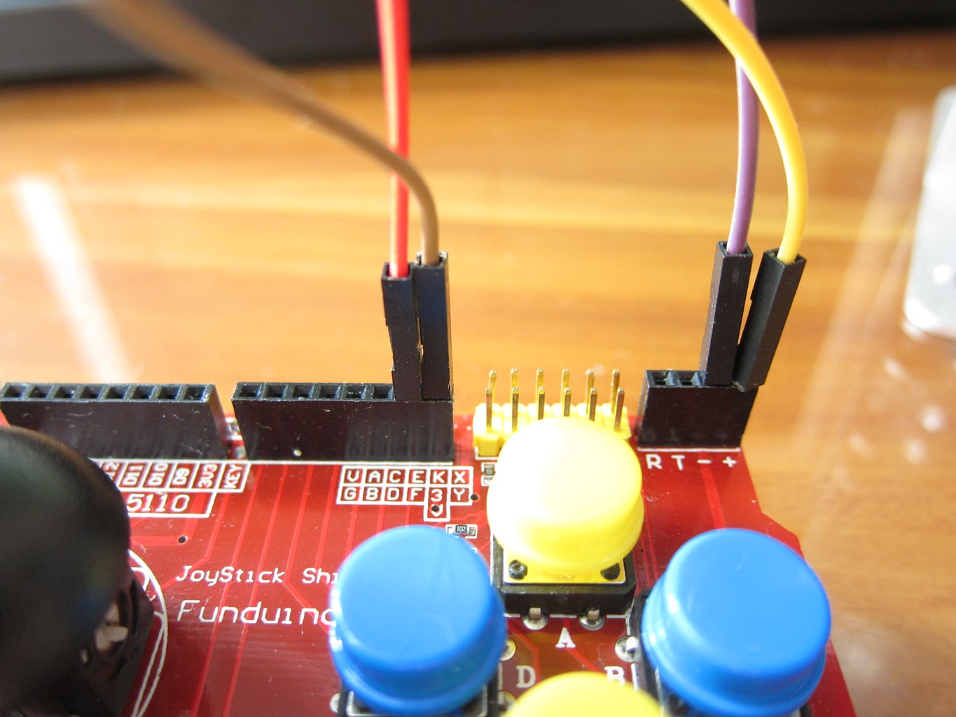
From servo controller to Joystick Shield
Pin GND > - on Joystick Shield
Pin 5V > + on Joystick Shield
RXD > Pin 0 on Joystick Shield
TXD > Pin 1 on Joystick Shield
Step 4: Testing Code
Next, I select A button to control the servo on the claw. When I press A button, the digital signal changes to 0 and the claw closes; when I release A button, the digital signal becomes 1 and the claw opens. I've referred to the table of PWM in the seventh project as follow:
Servo Lowest PWM Movement Highest PWM Movement
S1 500 right 2500 left
S2 500 up 2500 down
S3 500 down 2500 up
S4 500 down 2500 up
S5 500 anticlockwise 2500 clockwise
S6 900 open claw 1700 close claw
To control the servos with servo controller, we have to know the command and this is in the structure as follow:
#P ...........T
I want the claw closes in 1.5 second and we can sketch the code as follow:
#6P1700T1500
Servo controlling the claw is S6 and PWM of closing claw is 1700.
When I press A button, Arduino sends this command to servo controller via serial communication. Servo controller reads it and it instructs the claw to close.
int A_button = 2;
int B_button = 3;
int C_button = 4;
int D_button = 5;
int E_button = 6;
int F_button = 7;
int Analog = 8;
int x_axis = A0;
int y_axis = A1;
void setup()
{
Serial.begin(9600);
pinMode(A_button, INPUT);
pinMode(B_button, INPUT);
pinMode(C_button, INPUT);
pinMode(D_button, INPUT);
pinMode(E_button, INPUT);
pinMode(F_button, INPUT);
pinMode(Analog, INPUT);
}
void loop()
{
int A_button_state = digitalRead(A_button);
int B_button_state = digitalRead(B_button);
int C_button_state = digitalRead(C_button);
int D_button_state = digitalRead(D_button);
int E_button_state = digitalRead(E_button);
int F_button_state = digitalRead(F_button);
int Analog_state = digitalRead(Analog);
int x_axis_state = analogRead(x_axis);
int y_axis_state = analogRead(y_axis);
if (A_button_value == 1)
{
move(6, 900, 1500);
}
if (A_button_value == 0)
{
move(6, 1700, 1500);
}
}
void move(int servo, int position, int time)
{
Serial.print("#");
Serial.print(servo);
Serial.print("P");
Serial.print(position);
Serial.print("T");
Serial.println(time);
delay(time);
}
Before uploading this code, make sure both pin 0 and 1 are disconnected
from Joystick Shield. Otherwise the upload will fail. We can re-connect these two pins to Joystick Shield again after the sketch is uploaded.
Now you can control the claw by just pressing A button. You may also change the code in void loop() and test the buttons one by one.: D
Step 5: Modified Code
The test runs perfectly! But there is a problem: The claw opens when I release the button. If I wanna keep the claw closes, then I have to keep pressing the button. As a result, I place a value of PWM for each servo and add/minus 100 when I press the button.
int A_button = 2;
int B_button = 3;
int C_button = 4;
int D_button = 5;
int E_button = 6;
int F_button = 7;
int Analog = 8;
int x_axis = A0;
int y_axis = A1;
int value6 = 1000;
int value5 = 1000;
int value4 = 1000;
int value3 = 1000;
int value2 = 1000;
int value1 = 1000;
void setup()
{
Serial.begin(9600);
pinMode(A_button, INPUT);
pinMode(B_button, INPUT);
pinMode(C_button, INPUT);
pinMode(D_button, INPUT);
pinMode(E_button, INPUT);
pinMode(F_button, INPUT);
pinMode(Analog, INPUT);
}
void move(int servo, int position, int time)
{
Serial.print("#");
Serial.print(servo);
Serial.print("P");
Serial.print(position);
Serial.print("T");
Serial.println(time);
delay(time);
}
void loop()
{
int A_button_state = digitalRead(A_button);
int B_button_state = digitalRead(B_button);
int C_button_state = digitalRead(C_button);
int D_button_state = digitalRead(D_button);
int E_button_state = digitalRead(E_button);
int F_button_state = digitalRead(F_button);
int Analog_state = digitalRead(Analog);
int x_axis_state = analogRead(x_axis);
int y_axis_state = analogRead(y_axis);
x_axis_state = map(x_axis_state, 0, 1000, -1, 1);
y_axis_state = map(y_axis_state, 0, 1000, -1, 1);
if (A_button_state == LOW)
{
if (value6 < 1700)
{
value6 = value6 + 100;
move(6, value6, 100);
}
else
{
move(6, value6, 100);
}
}
if (B_button_state == LOW)
{
if (value6 > 900)
{
value6 = value6 - 100;
move(6, value6, 100);
}
}
if (C_button_state == LOW)
{
if (value5 < 2500)
{
value5 = value5 + 100;
move(5, value5, 100);
}
else
{
move(5, value5, 100);
}
}
if (D_button_state == LOW)
{
if (value5 > 500)
{
value5 = value5 - 100;
move(5, value5, 100);
}
}
if (E_button_state == LOW)
{
if (value4 < 2500)
{
value4 = value4 + 100;
move(4, value4, 100);
}
else
{
move(4, value4, 100);
}
}
if (F_button_state == LOW)
{
if (value4 > 500)
{
value4 = value4 - 100;
move(4, value4, 100);
}
}
if (Analog_state == LOW)
{
if (value3 < 2500)
{
value3 = value3 + 100;
move(3, value3, 100);
}
else
{
move(3, value3, 100);
}
}
if (y_axis_state == -1)
{
if (value2 < 2500)
{
value2 = value2 + 100;
move(2, value2, 100);
}
else
{
move(2, value2, 100);
}
}
if (y_axis_state == 1)
{
if (value2 > 500)
{
value2 = value2 - 100;
move(2, value2, 100);
}
}
if (x_axis_state == -1)
{
if (value1 < 2500)
{
value1 = value1 + 100;
move(1, value1, 100);
}
else
{
move(1, value1, 100);
}
}
if (x_axis_state == 1)
{
if (value1 > 500)
{
value1 = value1 - 100;
move(1, value1, 100);
}
}
}
Step 6: Result
After several modifications on the sketch (I have skipped several modifications as those results were not satisfied), finally I can control the robot arm with the Joystick Shield. Although I still haven't figured out some difficulties, e.g. I want to control both an increase and decrease of PWM on each servo with only one button, but in this project I have to do it with 2 buttons. It should be much simple to control it if I can find another way to encounter this problem. Please tell me if you know how to deal with it. Thanks a lot. : D


