

Introduction: Nandhopper 1-Bit Noise Synth


Make a cute + expressive 1-bit noise synthesizer with a logic gate and a few other spare parts.
Watch a demo video to get a better idea of what I mean, or listen to some improvisations: 321.
Step 1: Materials
Tools
- Soldering iron + solder
- Hot glue gun + glue
- Knife/razor
- Wire Cutter
- Breadboard
Materials
- 4093 (Quad, 2-input Schmitt trigger NAND gate)
- 1/8" stereo miniplug connector
- 9 V battery connector
- Small capacitors (I used 220 pF monolothic capacitors)
- Single sided copper clad
- Conductive foam (comes with microcontrollers and DIP chips)
- Wire
Extra
- Oscilloscope
- Power supply (for watching current draw)
- Multimeter
- Sound system or headphones
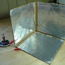
Step 2: Make FSRs


The interface to this device consists of four force sensing resistors. They can be anywhere from about 2x2 cm to 4x4 cm. If they're bigger, just make sure the wire is longer.
Plusea makes some really cool DIY FSRs, but I used my own style, because I don't have the same materials available. For Plusea's FSRs, you're working with around 200 ohms - 200 kiloohms max. For mine, you're working with 5-15 megaohms max. Commercial FSRs are in a similar range (e.g., this one is around 20 megaohms without a load). This maximum resistance is important to keep in mind when you're selecting capacitors.
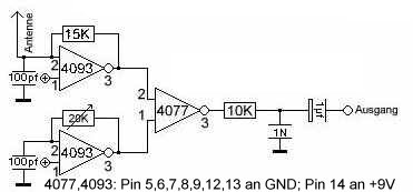
Step 3: Prototype: Make a Square Wave


There are a few ways to get a NAND gate to give you a square wave. We'll use a way that requires one gate, resistor, and capacitor per oscillator:
- Wire one input to high (9 V)
- Connect one input to ground via a capacitor
- Connect the output to the grounded input via a resistor
In short, if you use this circuit and change the resistance you can change the frequency. Furthermore, you can turn it on and off by wiring input 1 to ground instead of high.
Step 4: Prototype: Make the Circuit


- Figure out what you want in advance, and draw up a circuit that works like that.
- Make some sound, and start intuitively adding and removing components however you feel.
The first approach is a lot more predictable and repeatable, so I'll describe two layouts that have come from that perspective.
One layout just uses each of the four NAND gates as independent square wave synthesizers. In my experience, they're not genuinely independent and there is always some sort of leakage between the channels -- which can make things really interesting. Each pair of gates is mixed into one of the stereo outputs.
The other layout uses two stages: one driving oscillator, that is always running, and three oscillators stuck in a circular/triangular feedback loop. That's the one I breadboarded here.
Pick one of these, or design your own (or improvise your own, according to your ear).
Step 5: Solder Everything Together


Now that everything works on the breadboard, we're going to move it over to the chip.
Start with the power connector. Leave maybe ten centimeters of wire, just in case something goes wrong and you need to cut it off and reuse it. When you solder the ground and 9 V in place, it will help remind you where things are.
From here, I like "transplanting" the circuit: you have the breadboard next to the chip you're soldering onto, and slowly move components from the breadboard to the chip. This is one way to make sure you haven't forgotten anything. Make sure you don't forget that the orientation is different if your chip is upside-down and your breadboard is right-side-up!
Next, add the capacitors. I wrap the legs around the chip so it stays in place, then solder them on once they're where I want. One of the capacitors might have to stretch if it's going to ground, just make sure the leg doesn't touch anything it shouldn't.
Next, add any extra wires. If you're doing the independent oscillator design, you'll need wires for giving each gate its logic high.
Finally, add your resistors and FSRs. Resistors can be fit snugly under the chip, FSRs should be coming off the sides of the chip's pins.
Don't add the 1/8" connector yet, since you want to make sure the circuit works first. Solder some temporary connections (long wires) to the 1/8" connector.
Step 6: Plug It in and Finalize


Plug it in! Grab a 9 V battery (if you haven't already been using one), some headphones, and test it out. It should be outputting a 0-9 V signal, while sound normally runs at +/-1V. But sound systems also tend to have capacitors in line with the input that center things around 0 V and remove any DC bias. You should still be careful with volume: start with it off, and slowly turn it up.
As you improvise you might discover a lot of strange things: touching sensors together might cause weird sounds; depending on how you've wired it, touching the sensors without applying force might even cause some strange sounds.
If nothing works, check for broken connections or things in contact that aren't supposed to be in contact. Debugging these is probably more work than it's worth, and if it's not obvious you might be better off building a new one.
If everything works correctly, leave things plugged in and start hot gluing everything in place. Start with the audio connector, and then soldering "real" (shorter) connections between the chip and audio jack. Then hot glue everything that looks like it could ever come undone. This synth isn't meant to last for a long time, but the glue will help when you inevitably drop it. I leave things plugged in just to make sure I'm not breaking anything as I apply the glue.
Step 7: Variations and Notes
Variations
- Try using something that isn't a NAND, but still has a truth table that allows you to make oscillators (for example, XOR, NOR or NOT).
- Multiple Nandhoppers wired together: you've got ten fingers, right?
- A different embodiment: imagine a sphere covered in FSRs with the same NAND-based synth in the center.
- Try TTL instead of CMOS logic (running off a regulated 9 V battery, or some other power supply in the standard TTL range).
Notes
Thanks again to Dane Kouttron, who explained to me why this worked a long time ago.
If you have any comments, explanations of important things I didn't cover, or ideas for how to make a really responsive and varied noise synth out of a few components -- post below!


