

Introduction: Pi 3, 2 the MaX for Under £5 - Overclocking - Automatic 2 Speed Cooling


So this story begins a couple of weeks ago when i’m watching a youtuber called Andreas Spiess doing a brilliant video about pimping his pi with a UPS power pack, cooling and automatic shutdown. That gave me the idea to get started with my own little pi project. I wanted to squeeze more power from the Pi 3 while overclocking it but not have it fail or throttle the cores when the temperature started to rise. i also wanted the fan to come on in 2 stages as i didn't want lots of noice unless it needed to run at full tilt. So i thought, lets see what i can do and thanks to my new knowledge about how to connect a fan i could now get started.
Step1: From eBay i ordered a case for the pi 3, a fan kit, and a few mosfets and got to work.
The strategy was going to be:
Step2:
Overclocking Storage, CPU, etc and install the heatsinks.
Test to see if the Pi still worked :).
Step3:
Breadboard fan mod.
test fan mod.
Step4:
integrate fan kit to Pi case.
Put the kit togheter.
Step5:
- Write the code.
- Test it.
Step 1: BoM


- 1 x Pi 3 (Had already)
- 1 x Micro SD card - UHS (Had already)
- 1 x Case (eBay £1.03)
- 1 x Fan Kit (eBay £5.95 http://www.ebay.co.uk/itm/162243905715?_trksid=p2...
- 2 x MosFet FQP30N06L (eBay 5pcs £1.30)
- 1 x Resistor fan 22 Ohm (Had already)
Alternatively get parts cheaper separately:- - HeatSinks (eBay £0.99 http://www.ebay.co.uk/itm/162243905715?_trksid=p2...
- - Fan (eBay £1.09 http://www.ebay.co.uk/itm/KIT-DC-5V-0-2A-Cooling-...
In Addition:
- You will needs some tools to cut the case and drill the holes to fit the fan and the other components.
- Soldering iron for the components, etc . . .
Step 2: Overclocking the Pi
In this step you will have to edit the Pi's "/boot/config.txt" file and insert the entries below in order to squeeze the power of your system. I simply copied and pasted the below in to the file as its shown below.
Save the file when done and reboot, for the changes to take effect.
It is not recommended to do all the changes in one go, but i was impatient and these not too crazy figures worked for me first time.
It is recommended NOT to try this with a regular non-UHS SDHC card, i had a high speed card already.
total_mem=1024
arm_freq=1300<br>gpu_freq=500
core_freq=500<br>sdram_freq=500
sdram_schmoo=0x02000020
over_voltage=2<
sdram_over_voltage=2
dtparam=sd_overclock=100
i found that the arm_freq of 1300 mhz was the highest i could go for a stable Pi as with 1400 mhz it got unstable and froze up pretty quick, even 1350 mhz it was not reliable enough.
Here is a link to the full awesome article i got it from: https://github.com/RetroPie/RetroPie-Setup/wiki/Ov...
by Adrian Moisey
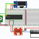
Step 3: Breadboard the Components and Test It's Working


Next up was to install the heatsinks and breadboard up the components to see if i could get it to work.
i initially ordered the same kind of mosfets that Andreas used from eBay china, but when i got them it turned out that they where fake and did not adhere to the same specifications so i ordered a couple of "Fqp30n06l" and they worked a charm.
The key here is that the Pi pin voltage is 3.3v and the fake mosfets i got initially didn't turn on until around 4.5v
Testing:
using the raspberry pis built in gpio commands i tested the functionality by turning on and of the pins. in my case pin 26 and 27.
in the command prompt/terminal window:
gpio readall -> shows you the layout and configuration as shown in the image
gpio mode 26 output -> sets the relevant pin (26 in this case) to be configured to output, so we can set it high and low, or 1 or 0.
gpio write 26 1 -> will turn on the relevant pin and put 3.3v out on it.
In my case this will tun on the fan full tilt using the mosfet with no resistor. writing pin 27 high will turn on the fan in a slow speed using the other mosfet with the resistor.
.
Step 4: Integrate the Kit Into the Case, Put It Togheter and Test Again.


This is where you will need to use some of the tools i mentioned earlier and i will assume you know how to use a drill, soldering iron etc.
i started by measuring out the place where the fan was going to go. this was a little fiddly as i wanted the fan and the components inside the case for a sleeker look.
So i drilled holes, cut wires, soldered and screw the components in and once i was happy i tested again.
this time it wasn't working so it was back to trouble shooting. i eventually found the ground wire was the issue and replaced that.
testing was performed like the last step.
Step 5: Write the Code, Implement and Test It.
i wanted to learn this myself so i didn't use Andreas code as i needed to have 2 speeds, so here is my python code for the Pi:
#!/usr/bin/env python3
import os
import time
from time import sleep
import signal
import sys
import RPi.GPIO as GPIO
fanhigh = 0
fanlow = 0
ctemp = 0
GPIO.setmode(GPIO.BCM)
GPIO.setup(12, GPIO.OUT)
GPIO.setup(16, GPIO.OUT)
GPIO.setwarnings(False)
while True:

    res = os.popen('vcgencmd measure_temp').readline()
    ctemp =(res.replace("temp=","").replace("'C\n",""))
    ctemp = float(ctemp)
##    print("Cpu temp= {0}".format(ctemp)) #Uncomment here for testing
##    print "fanLow= " + str(fanlow)
##    print "fanHigh= " + str(fanhigh)
##    print ""
    if ctemp>55 and fanlow==0:
        fanlow = 1
        GPIO.output(16, True)
        GPIO.output(12, False)
##        print "> 55 c"
##        print "fanlow = 1"
##        print "gpio pin 27 ON"
##        print ""
    if ctemp<45 and fanlow==1:
        GPIO.output(16, False)
        GPIO.output(12, False)
        fanlow = 0
        fanhigh = 0
##        print "<45c and fanlow set to 0"
##        print "fanlow = 1"
##        print ""
    if ctemp>50 and fanlow==1 and fanhigh==1:
        fanlow = 0
        fanhigh = 0
        GPIO.output(16, True)
        GPIO.output(12, False)
##        print ">50 c "
##        print "fanlow = 0"
##        print "fanhigh = 0"
##        print "gpio pin 27 ON"
##        print "gpio pin 26 OFF"
##        print ""
    if ctemp>65 and fanhigh==0:
        GPIO.output(12, True)
        GPIO.output(16, False)
        fanhigh = 1
##        print ">65c  and fanhigh set to 1"
##        print "fanlow = 1"
##        print ""
    sleep(5)
i save the file as fan.py. I followed Andres advice and put it in a scrip folder.
The print statements are can be uncommented for troubleshooting.
After testing it to make sure it did what i wanted i i created the command file launcher.sh and saved that to the same folder.
#!/bin/sh
# launcher.shsudo python /home/pi/scripts/fan.py &
The & at the end tells the system to runt he script in the background.
Next step is to make the bash script executable by running -> chmod 755 launcher.sh in the terminal window on the Pi.
Next up is to create a crontab entry so that the launcher.sh will be started automagically when you reboot :)
In the terminal window type: sudo contab -e
Then add at the end of the flle: @reboot sh /home/pi/scripts/launcher.sh
Save the crontab file and Reboot.
I used ps aux | grep fan* to make sure that the file was started and showed up in the task list and gpio readall to see that the pins was set to output, confirming the script was running.
i then kicked off the stress test: sysbench --test=cpu --cpu-max-prime=12500 --num-threads=4 run to see that the fan comes on and goes of as it should and after a bit of tweaking, YAZZY is working !!!!
Step 6: Thanks To:
- Andreas Spiess for the inspiration and assistance.
Please go and check his YouTube channel out here:
- Adrian Moisey at GitHub: https://github.com/RetroPie/RetroPie-Setup/wiki/Ov...


