

Introduction: Project 2 : Photo Resistor


As we have done the most basic and easiest project of Arduino the, Led Blink its time we move a little more further. Today we are going to use the Photo resistor which is an instrument which can be understood by its another name, LDR which expands to Light Dependent Resistor. Photo resistor is a light controlled resistor in which resistance decreases with incident light increasing. So they are inverse in nature. Let's try out this photo resistor today with our Arduino Board.
Step 1: What You Require?


The requirements for this program are the same as before but with just one new inclusion in it.
- Arduino Uno or Arduino Mega 2560 (They are the beginning boards of Arduino)
- Jumper Wires (Male to Male)
- Led
- Photo Resistor
- Breadboard
- 10 K (more preferable) or 1k resistor
- Cable (To connect board with your Computer for uploading the Program)
- Arduino Program (Downloadable from https://www.arduino.cc/en/Main/Software
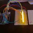
Step 2: Build Your Circuit and Know Why Is It Designed So?


This Project's Circuit can be divided into 2 which is the LED and the other is Photo Resistor.The Led Circuit is just like the previous Instructable. The Photo Resistor part is what we are going to learn in this instructable.
Before we proceed let's discuss one more thing. As we know that there are only 4 GND's (Source of Negative Energy) in the whole Arduino Board we will learn how to make it more. If we directly put the Jumper Wire from the GND to the Led's shorter rod then we can power up to only 4 Led's. But we will learn this new method to empower infinite units like Led's with GND's rather than limiting it to 3 or 4. In the above diagram of Breadboard you see the 4 parts of the board. The end 2 parts have Different Rows for Negative and Positive Energy. If we connect one GND to the negative row of one of the end row then the whole negative row is powered by GND. Then insert one end of the Jumper Wire to any of the Coloumn in the Powered Negative Row and put the other end in the Negative part of any electrical unit such as led, photo resistor, etc. You can use the positive one for powering with the 5V part of Arduino.
Now we are going to learn the Photo Resistor part of the Circuit. At one end of the Photo Resistor insert one end of the resistor (10 K mostly preffered) and power the other end with negative energy or GND. At the end of the Photo Resistor where also the Resistor is connected connect a Jumper Wire with Analog Read (I used A0). Analog Read is like PWM with distinct identification but Analog Read is used for Values, Else and If which we will learn in the programming section.
Now at the other end of the Photo Resistor connect it with positive energy from 5V and not from the distinct PWM Pins.
Step 3: Now for the Software and Understanding It

Now let's get on with the Software. Let's keep the Led software away from brief description because we already discussed about it in the previous Instructable. The new terms we are going to learn are int (integer), const int (constant integer), if and else.
- int is the programming unit for integer which can be of any value. We will see how it is used later.
- const int is used to subsitute a name with pins like PWM and Analog Read.
- if is a condition in which you describe a situation and if it occurs what will happen.
- else is a condition which will happen if the described situation does not occur.
The Program is like this:
const int pResistor = A0;
const int LED=9;
int value;
void setup(){
pinMode(LED, OUTPUT);
pinMode(pResistor, INPUT); }
void loop(){
value = analogRead(pResistor);
if (value > 300)
{
digitalWrite(LED, LOW); }
else{
digitalWrite(LED, HIGH); }
delay(500); }
Try Changing the Value and see the what it changes. Then you will understand the programming unit int or integer.b
Step 4: Congratulations

Congratulations, thanks a lot for following up. Follow me and comment if you have made the project, thanks a lot again.


![Tim's Mechanical Spider Leg [LU9685-20CU]](https://content.instructables.com/FFB/5R4I/LVKZ6G6R/FFB5R4ILVKZ6G6R.png?auto=webp&crop=1.2%3A1&frame=1&width=306)


