

Introduction: Propeller Display


This project is a special kind of circular LED display. With the help some mechanical assembly, LED count, hardware requirement, and hence overall cost is cut to very affordable price. Also, maintenance and repairing of the display is so easy, that anyone having a little electronics knowledge, can take care of this. All the synchronising can be implemented through software.
First of its kind, made using the 20-pin 8051 series microcontroller, this project use the principle of Space Multiplexing. This propeller display is mechanically scanned and displays the characters in digital format. Made from scrap it can be used anywhere and everywhere and the most amazing fact about this display is it’s crystal clear display. This display consists of just 8 bright LEDs which are rotated to show the display.
For building this project, requirement is just a small 20 pin microcontroller, a position encoder, and LEDs. This display can show the messages, which will require a whopping 525 LEDs. So hardware and cost minimisation is achieved.
Step 1: What Is a Persistence of Vision (POV)...?

Persistence of vision is the theory where an afterimage is thought to persist for approximately one sixteenth of a second on the retina, and believed to be the explanation for motion perception; however, it only explains why the black spaces that come between each "real" movie frame are not perceived. The true reason for motion perception is the phi phenomenon while the true reason for perception of continuous light is Flicker fusion.
You can read more about POV on this ink
Step 2: Building Materials.....


Here are the list of things required for this Project.
** I have increased the quantity in the list as it might be possible that some of the components gets broken during the connection process
- Zero PCB -- Quantity = 3 medium size
- Connecting wires (buy it in bunch)
- LED's preferably white colour, or any colour you want for your message display -- Quantity =10
- AT89C2051 microcontroller. its a 20 pin microcontroller wiich has a single port (I/O pins)
- Crystal for microcontroller (4.9152 MHz)
- Voltage Regulators (LM7805- microcontroller power supply)
- Capacitors.
- 1000 µf 25 volts -- Quantity = 2 (electrolytic)
- 10 µf 16 volts -- Quantity = 2 (electrolytic)
- 33 pf -- Quantity = 4 (ceramic)
- Resistors.
- 220 Ω -- Quantity = 10 (are basically connected to LED's to adjust its perfect brightness)
- 10 kΩ -- Quantity = 4
- 1 Ω -- Quantity = 2
- MOC 7811 (motorola interrupt circuit)
- Tape Recorder Flywheel
- 12 volt DC motor
- 12 volt Adapter (we can also use an adjustable voltage adapter)
- Soldering gun and soldering wire.
- Microcontroller program burner. (interfacing hardware between your pc and microcontroler to dump your programs in microcontroller.
Step 3: Display Functioning


LED's are arranged in a straight line over a propeller kinda structure so if the LED's are kept on and making the propeller rotate we would see a circular disc kind of display.
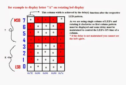
To make an alphabet display through the LED's we need to switch on and switch off our LED's in a patterns as required for an alphabet.
I have attached an image of letter A how to display through the rotating LED's.
Our eyes cant focus on very fast moving objects so we see the fast moving objects as a blur. Similarly taking the advantage of fast rotating propeller and led's blinking in a patterns we are able to display numbers alphabets and many more things on a propeller display.
The images in this section are self explanatory.
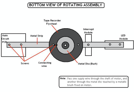
Step 4: Block Diagram and Physical Overview


The block diagram represents the overall relationship between each components connected in this project.
The microcontroller is interfaced with an interrupt circuit and an output port has been connected to 8 LED's.
The power supply circuit incorporates voltage regulator for microcontroller and connected to the microcontroler in such a way that a metal wire constantly slips over the flywheel (like a brush in a motor) completing path to transfer the power to the Microcontroller.
Step 5: Circuit Diagram


This circuit diagrams give you the brief description of the connections to be made between each and every components of this project.
While making connections to the LED's make sure that you are connecting the right terminal I mean if the programming is in Positive logic then all the anode need to be connected in microcontroller pins through the resistor and the cathode is connected to all LED's cathode should be grounded otherwise like the negative logic used in my programming we need to connect anode terminal of all LED's together and the cathode needed to be connected to each respective pins of microcontroller through resistor.
Power to microcontroler can be given in 2 ways.
- We can place a 9 volt battery over the rotating module and connect the voltage regulator to drop the voltage to 5 volts for microcontroller
- We can have an arrangement like a brush of a motor which constantly slips over commutator to provide power to the windings similarly the whole module can be mounted over a metal flywheel and a wire from the main power supply can slip over the flywheel to provide power tho the microcontroller module.
I find the second option more fruitful as adding a battery over the module can cause in additional weight which can also cause in decrease of speed as the propeller display can provide a sharp image(display) at high speed.
Step 6: Programming

I did the programming on KEIL IDE as its the best one for microcontrollers.
We can even display numbers, a clock animation or a picture animation on a propeller display..
But all you need is the basics of how to code your microcontroller and the pattern to display a letter.
so constantly working on your logic and improving your code can definitely help you if you want to display a complex images too :)
This software also allows you to make a .HEX file after your programs do not have any errors and also you can change the crystal speed while creating the .HEX file.
Step 7: Pseudo Code


1. Code for the timer 0 interrupt
interr: ;T0 interrupt
cjne r6,#0ffh,sk
mov r6,#00h
acall disp
sjmp sk1
sk:
mov r6,#0ffh
sk1:
clr tf0
ret
This interrupt is intended for displaying each segment at regular time interval. The interrupt gets executed after each timer 0 overflow, which overflows at adjustable time intervals.
2. Code for the External Interrupt
; EXT0
interruupt
interr1:
clr tr1
clr tr0
mov a,th1
mov r1,a
mov a,tl1
mov r0,a
mov r3,#00h
mov r2,#160
acall div16_16
mov a,r2
subb a,0ffh
mov th0,a
mov tl0,a
mov th1,#00h
mov tl1,#00h
setb tr1
setb tr0
mov r0,#23h
mov r5,#00h
mov r6,#00h
ret
This interrupt performs the basic task of synchronization. It also
resets the character pointer (R0), the segment pointer (R5). Another thing performed in this interrupt is that, the previous time gets divided into number of segments, and the concluding result will be stored in the timer register TH1
Step 8: Programming Your Microcontroler


After verifying your program you can generate .HEX file which can be burned to the microcontroller.
Atmel programmers are easily available in a local electrical and electronics shops. This programmer is capable of programming 40 pin as well as 20 pin microcontrollers.
Proload Software is generally provided with the programmer itself to interface your pc to the microcontroller. this is a very simple software easy to understand and asks you for your .HEX file location.
Make sure the com port number in the software is correct. If you do want to check it then open your device manager and check for the com ports, you will get the idea.
Step 9: Hardware Model


These are the pics of my propeller display model
This model can be also be implemented for displaying the time or animation.
*Note - make sure you balance your propeller before attaching the flywheel in the centre of gravity. If the balancing is not done properly then it can cause your module to wobble and on high speeds it can actually cause damage to the mounted components.
Step 10: The HEX File

This is a .HEX file which you can directly dump in your microcontroller.
The .a51 file can be opened in keil software to see the actual code.
I have also attached a simple code (propeller.c) for understanding purposes. This is a simple code which can be edited into keil software and can be customised according to the requirements.

Step 11: Scope of Propeller Display


Implementation of this technology can be done in creating innovative advertisements on a bicycle wheels.
It can also be implemented in homes as a propeller clock
This module can be customised with coloured LED's to create a coloured display which can be more appealing and can also be used to replace big power consuming displays.
It is also useful to hobby projects enthusiasts.
**The images in this step are taken from Google as to demonstrate the scope of propeller display.

Participated in the
Mind for Design


![Tim's Mechanical Spider Leg [LU9685-20CU]](https://content.instructables.com/FFB/5R4I/LVKZ6G6R/FFB5R4ILVKZ6G6R.png?auto=webp&crop=1.2%3A1&frame=1&width=306)


