

Introduction: RGB Binary Clock

This is my first Instructable. I was currently working on another project, a POV clock(also known as a propellor clock), but i got stumped with the pcb making process and the induction power gap but thats another story i will finish hopefully soon. I just sort of put this together last night out of boredom. This is, as the title suggests, an RGB Binary Clock powered by Arduino, oh woop-de-doo. I did this on a bread board as I don't intend of keeping it, but you can definitely fit it up on a pcb and find an enclosure for it and make it look amazing.
I am NOT gonna explain much, I'll try to keep this as "NOOB" friendly as possible as I am quite the novice my self.
The basis of this project consists of an Arduino reading from the RTC chip (DS3231) every second. It then does some things and determines what LEDs go on or off. After that, it sends the information to the daisy-chained 74HC595 shift registers that control the LEDS.
I also included a potentiometer that determines the brightness of the leds because it was too bright at night.
Step 1: The Parts
The List:
16x RGB Common Anode Leds (Cathode will work with a tweak of the code)
16x 150 Ohm Resistors
32x 100 Ohm Resistors
6x SN74HC595 Shift Registers
1x Arduino (I used NANO)
1x DS3231 Real Time Clock
1x 5k Ohm Potentiometer
1x 100uF Capacitor (you can do without if not battery powered)
Assorted Cables
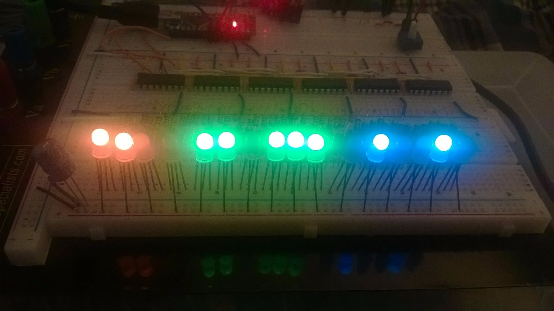
Step 2: Construction: Wiring Up the LEDs


Place the shift registers on the bread board, you can wire it up like I have done if you see the images. Please look at the 595 pinout for reference of what I'm about to say.
Pin 13 OE needs to be Grounded.
Pin 10 *SRCLR needs to be pulled up to VCC
PIN 8 is Grounded as usual
PIN 16 is VCC
ALL PINS 11 are connected to each other
ALL PINS 12 are connected to each other
To daisy chain to the next register, you connect PIN 9 *QH from the first register to PIN 14 SER of the next and repeat.
The FIRST register's PIN 14 SER is connected to the Arduino so don't worry about it just yet.
The RGBs have 4 pins. The notch indicates the facing. With the notch facing left, the pins should read R + G B
bend the Vcc pin back if you want to wire it like i did. Refer to the picture. The Red diode requires the 150 Ohm resistor whilst the other two can use the 100 Ohm.
By the way if you get lost with this, you can check out the source where I got it from. This is from elacojobs shiftPWM library. You can read all about it here.
http://www.elcojacobs.com/using-shiftpwm-to-contro...
credit goes to him here.
Step 3: Construction: the Rest


So place in the NANO into the board. Make connections for VCC and GROUND to the power banks on the bread board.
Jump PIN 13 of the Nano(mega 52, leo ICSP3) to PIN 11 on the shift registers. Anywhere since they're all connected together. Do the same PIN 11(mega 51, leo ICSP4) of the Nano and PIN 12 on the registers.
PIN 14 SER of the first shift register in the chain is to be jumped to PIN 8 on the Nano.
The RTC chips SDA and SCL wires need to be connected to the Arduino's own SDA and SCL pins which for the Nano and UNO are pins A4 and A5 respectiely. They are different for the Mega and Leonardo. Mega uses 20 and 21 respectively whilst the Leo uses 2 and 3. Make sure to power the RTC by connecting the VCC and Ground pins.
The potentiometer is quite easy. There are 3 pins connect VCC or Gound to the left pin, the opposite to the right pin and the middle pin is the data. Middle pin goes to A7 on the arduino as i assigned in the code.
That's pretty much it for wiring.
Step 4: RTC Time Set and Code

Please get the shiftPWM library from elacojobs. Thanks to him for his great contribution.
Get it here: https://github.com/elcojacobs/ShiftPWM
If you have just gotten a fresh DS3231 RTC chip and you need to set up the correct time, you can do so with this sketch. just un-comment if its not already done so and put the corresponding data. I've put some comments that help you understand the format in the sketch. the highlighted stuff is just showing what it would look like if i set the time to todays date at that time that my computer shows. The arduino takes about 9 secs or so to upload a sketch, It's different for everyone I guess, so you might want to first time the uploading sketch duration and then do it, in my case, 9 secs before the predetermined time you put in the code so you can get it really precise if you're ocd about it. After you upload the sketch and you verify the time in the Serial Monitor, you can either re-upload the sketch with the settime command commented or just upload the binary clock sketch to finish this up.
If you want a faster color transition, feel free to tweak the code.
While writing this, an idea just popped into my head. I'll try to add a speaker and make it play sounds like a grandfather clock second tick or/and the hourly bell tower jingle. That'll be on my long list of to-do things that take a while for me to actually do.


![Tim's Mechanical Spider Leg [LU9685-20CU]](https://content.instructables.com/FFB/5R4I/LVKZ6G6R/FFB5R4ILVKZ6G6R.png?auto=webp&crop=1.2%3A1&frame=1&width=306)


