

Introduction: RGB LED Tutorial (using an Arduino) (RGBL)
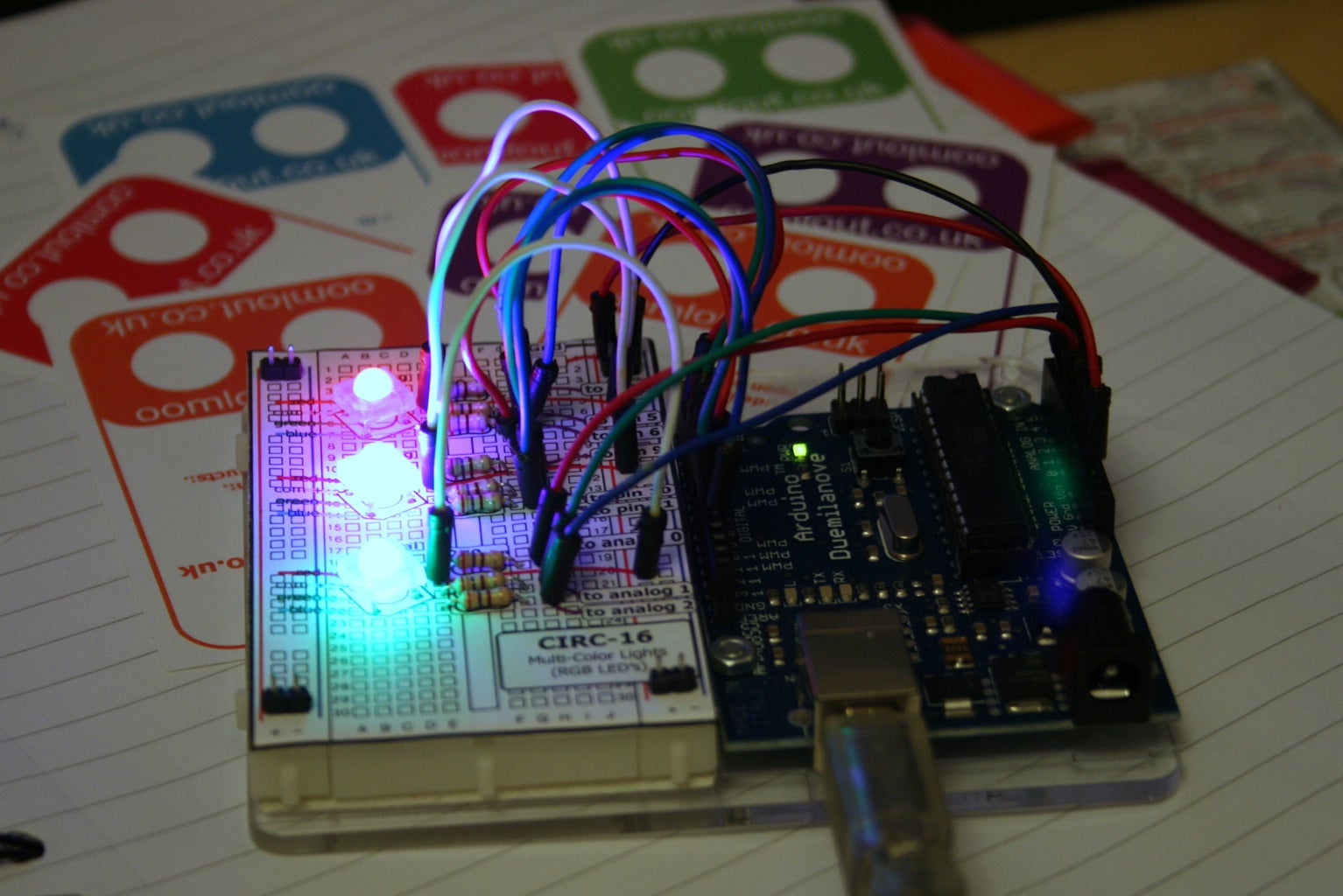


LEDs are great. But with any project there comes a point where flashing is simply not enough. For these cases an RGB (Red, Green, BLue) LED is the answer.
With an RGB LED you'll be able to produce any colour glow your heart desires.
At first using an RGB LED seems quite complex, but it quite quickly becomes clear that its no more difficult than controlling one of their single colour counter parts.
What follows is a quick guide to get you started controlling an RGB LED first with wires then with an Arduino microcontroller.
If you'd like to jump ahead to any part here's your chance.
Step 1 The Parts
Step 2 Testing
Step 3 Arduino Controlled Example Circuit
Step 4 Digital Control of Colour
Step 5 Analog Control of Colour
(Shamless Plug)
Interested in getting a few RGB LEDs to play around with and in the UK? a component bundle can be bought at our online store oomlout.co.uk
Step 1: Parts
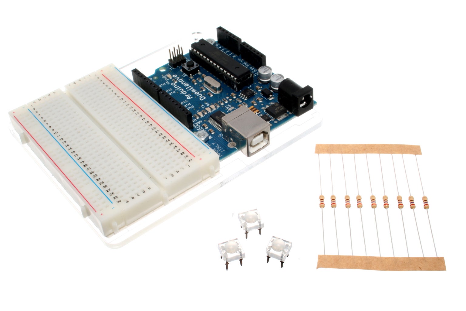
RGB LED (common anode)
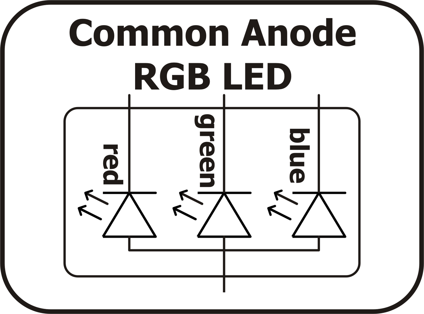
- A common anode RGB LED is nothing more complicated than three one colour LEDs (one red, one green, and one blue) housed in a single package.
- Rather than having 6 leads (a cathode and anode for each LED) it has only 4 one cathode for each colour, and one common anode. (see the schematic diagram below)
- A common anode RGB LED is the most popular type. It is most commonly found in either a 5mm bulb size or as a 5mm pirahna form factor.
- Most LEDs are designed to work with a voltage between 1.5v and 3v. As most microcontrollers (including the Arduino) operate on 5 volts a current limiting resistor is required.
- Consult your LEDs datasheet for maximum ratings but we like to use 270 ohm resistors. This limits the current to ~20mA, well within most LEDs and microcontroller ratings.
- A great open source microcontroller platform (for more details visit arduino.cc)
Step 2: Testing

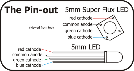
Consult your RGB LEDs datasheet for its pin-out or below are the two most common RGB LED form factors and pin-outs.
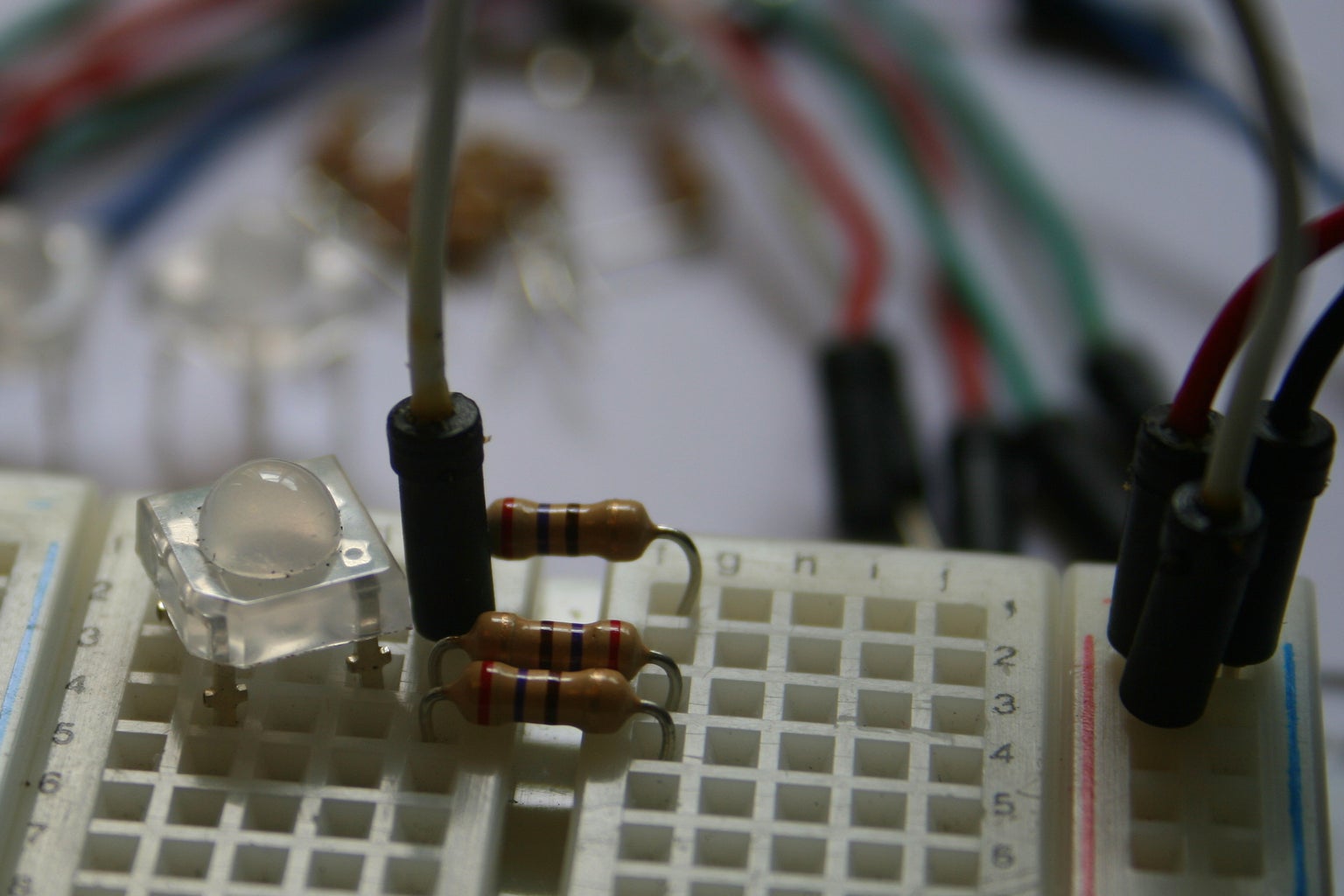
Wire up the Test Schematic (below)
- Plug the RGB LED into your breadboard
- Connect a current limiting resistor to each of the three cathodes
- Connect the common anode to 5V (5 volts)
- Test each color by connecting its current limiting resistor to ground (GND)
- Experiment with colour mixing a little by powering multiple elements at once
Step 3: Example Circuit

Time to move on to controlling your RGB LEDs with an Arduino.
For the example code to follow you'll need three RGB LEDs and 9 current limiting resistors (avaliable for purchase in the UK from oomlout.co.uk )
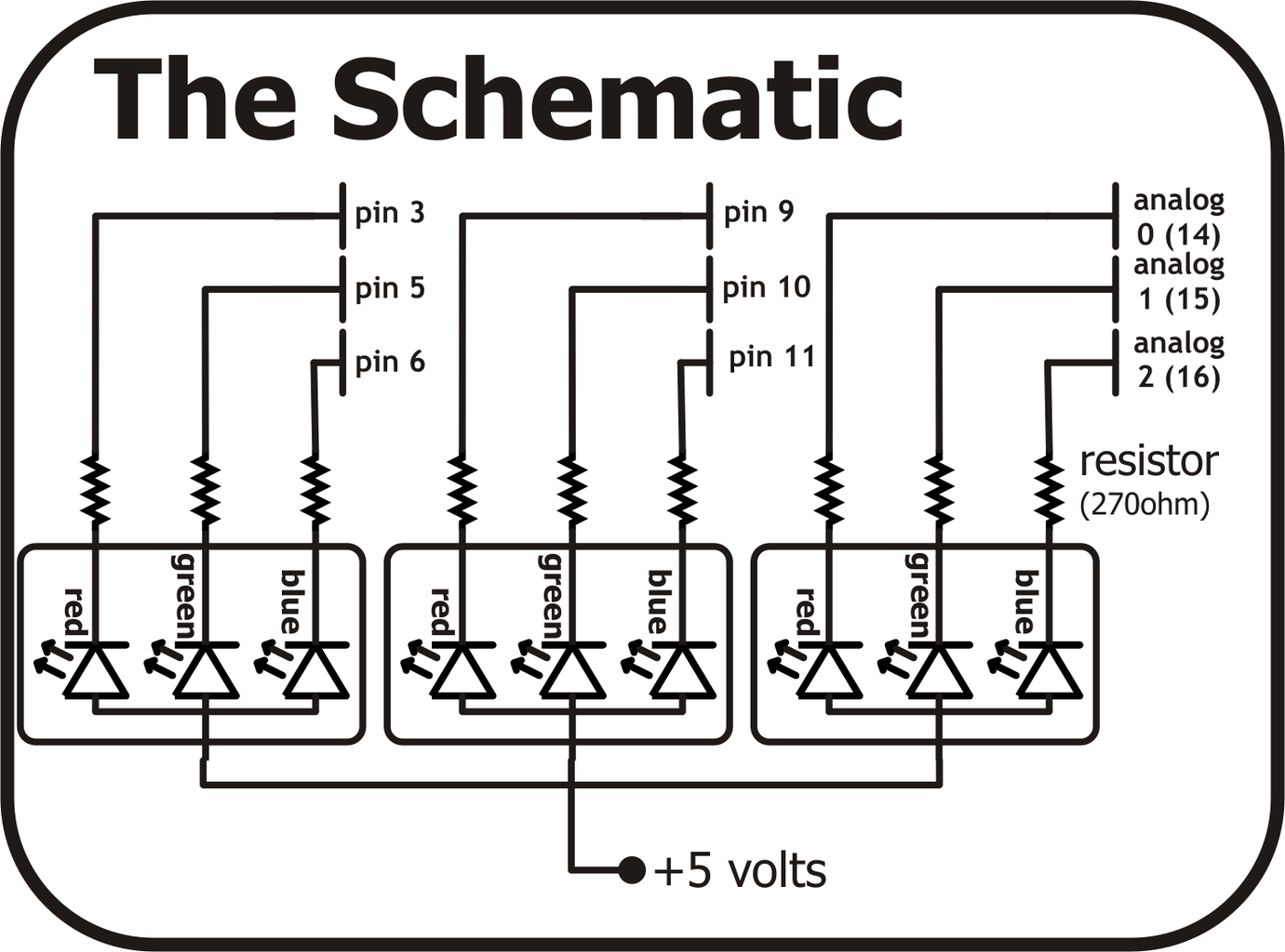
Wire up the circuit below.
There are two ways to do this. For the more advanced consult the schematic below.
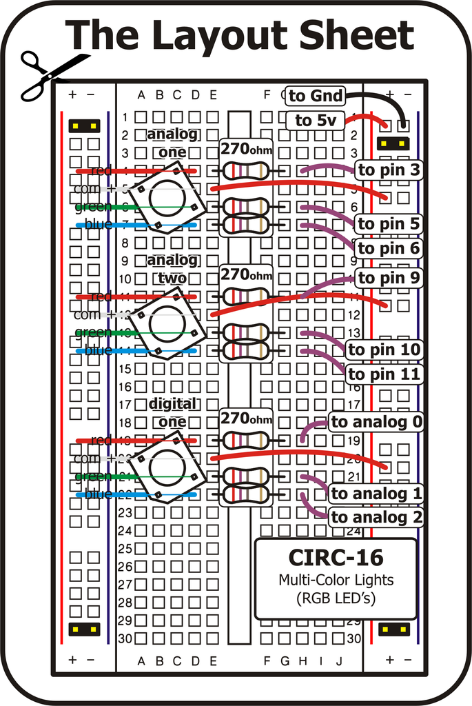
Or for the less advanced you can download a breadboard layout sheet (the pdf below). Print this out and lay it over your breadboard for convenient component placement.
Attachments

Step 4: Digital Arduino Code

But don't take our word for it download the code below and get playing. To do this simply...
- Copy the code below and paste it into a an empty Arduino sketch.
- Compile and upload the sketch to your Arduino board.
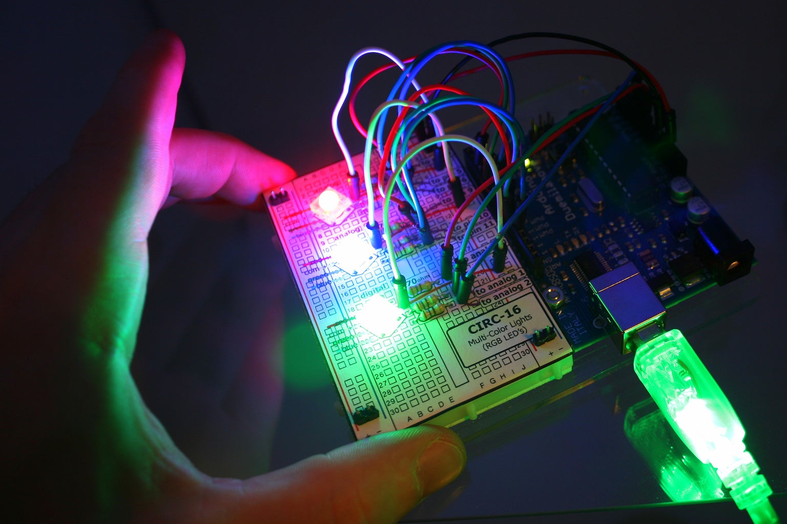
- Enjoy as your three LEDs light up Red, Green, and Blue.
- If you go to the loop() section of the code under example 1 you can see where you change the colors. Try a few other variations
- To see how we control each LED look at the setColor() function.
- Next comment out (add //) to the three lines of example 1.
- Un-comment (delete //) from in front of every line in the Example 2 section of the loop() code
- Upload this to your board and watch as your three LEDs change colour randomly.
- Play around with the code to see how it works and make your own fun color functions.
Appendix 1: _RGBL_Digital.pde
//--- bof RGBL - RGB Digital Preamble//RGB LED pinsint ledDigitalOne[] = {14, 15, 16}; //the three digital pins of the first digital LED 14 = redPin, 15 = greenPin, 16 = bluePinint ledDigitalTwo[] = {9, 10, 11}; //the three digital pins of the first digital LED 14 = redPin, 15 = greenPin, 16 = bluePinint ledDigitalThree[] = {3, 5, 6}; //the three digital pins of the first digital LED 14 = redPin, 15 = greenPin, 16 = bluePinconst boolean ON = LOW; //Define on as LOW (this is because we use a common Anode RGB LED (common pin is connected to +5 volts)const boolean OFF = HIGH; //Define off as HIGH//Predefined Colorsconst boolean RED[] = {ON, OFF, OFF}; const boolean GREEN[] = {OFF, ON, OFF}; const boolean BLUE[] = {OFF, OFF, ON}; const boolean YELLOW[] = {ON, ON, OFF}; const boolean CYAN[] = {OFF, ON, ON}; const boolean MAGENTA[] = {ON, OFF, ON}; const boolean WHITE[] = {ON, ON, ON}; const boolean BLACK[] = {OFF, OFF, OFF}; //An Array that stores the predefined colors (allows us to later randomly display a color)const boolean* COLORS[] = {RED, GREEN, BLUE, YELLOW, CYAN, MAGENTA, WHITE, BLACK};//--- eof RGBL - RGB Digital Preamblevoid setup(){ for(int i = 0; i < 3; i++){ pinMode(ledDigitalOne[i], OUTPUT); //Set the three LED pins as outputs pinMode(ledDigitalTwo[i], OUTPUT); //Set the three LED pins as outputs pinMode(ledDigitalThree[i], OUTPUT); //Set the three LED pins as outputs }}void loop(){/* Example - 1 Set a color Set the three LEDs to any predefined color*/ setColor(ledDigitalOne, RED); //Set the color of LED one setColor(ledDigitalTwo, GREEN); //Set the color of LED two setColor(ledDigitalThree, BLUE); //Set the color of LED three/* Exampe - 2 Go through Random Colors Set the LEDs to a random color*/ //int rand = random(0, sizeof(COLORS) / 2); //get a random number within the range of colors // setColor(ledDigitalOne, COLORS[rand]); //Set the color of led one to a random color //rand = random(0, sizeof(COLORS) / 2); //Set the color of LED 2 to a random color // setColor(ledDigitalTwo, COLORS[rand]); //rand = random(0, sizeof(COLORS) / 2); //Set the color of LED 3 to a random color // setColor(ledDigitalThree, COLORS[rand]); //delay(1000); }/* Sets an led to any color led - a three element array defining the three color pins (led[0] = redPin, led[1] = greenPin, led[2] = bluePin) color - a three element boolean array (color[0] = red value (LOW = on, HIGH = off), color[1] = green value, color[2] =blue value)*/void setColor(int* led, boolean* color){ for(int i = 0; i < 3; i++){ digitalWrite(led[i], color[i]); }}/* A version of setColor that allows for using const boolean colors*/void setColor(int* led, const boolean* color){ boolean tempColor[] = {color[0], color[1], color[2]}; setColor(led, tempColor);}Step 5: Analog Arduino Code

To do this each LED requires 3 PWM pins. As the Arduino has only 6 PWM pins only two RGB LEDs can be controlled this way at a time.
In terms of the code we will use the analogWrite(pin, value) function, for more details visit the code reference on Arduino.cc )
To get playing with the your LEDs in an Analog manner simply...
- Copy and paste the code below into an empty Arduino sketch
- Compile and upload the sketch to your Arduino board
- Example one will start by turning the LED magenta (you can then play around with the colour to change it to other presets, or define your own)
- Next comment out the Example 1 line (add //)
- Un-Comment Example 2 (delete the //)
- Compile and upload the example to your board.
- Now watch as your LED turns a whitish green colour, change the numbers in the tempColor[] array to change the displayed colour
- Comment out Example 2 (add //)
- Uncomment Example 3 (delete the //)
- Compile and upload the program to your board
- Watch as the LED fades from Red to Green To Blue. To see how this is accompished look to the fadeToColor() function
- Next get coding and making your own fun colour changing programmes
Appendix 1: _RGBL_AnalogTest
//---bof---RGBL-Analog Preamble//RGB LED pinsint ledAnalogOne[] = {3, 5, 6}; //the three pins of the first analog LED 3 = redPin, 5 = greenPin, 6 = bluePin //These pins must be PWMint ledAnalogTwo[] = {9, 10, 11}; //the three pins of the second analog LED 9 = redPin, 10 = greenPin, 11 = bluePin //These pins must be PWM//Defined Colors (different RGB (red, green, blue) values for colors//(to add your own ie. fuscia experiment and then add to the list)const byte RED[] = {255, 0, 0}; const byte ORANGE[] = {83, 4, 0}; const byte YELLOW[] = {255, 255, 0}; const byte GREEN[] = {0, 255, 0}; const byte BLUE[] = {0, 0, 255}; const byte INDIGO[] = {4, 0, 19}; const byte VIOLET[] = {23, 0, 22}; const byte CYAN[] = {0, 255, 255}; const byte MAGENTA[] = {255, 0, 255}; const byte WHITE[] = {255, 255, 255}; const byte BLACK[] = {0, 0, 0}; const byte PINK[] = {158, 4, 79}; //---eof---RGBL-Analog Preamblevoid setup(){ for(int i = 0; i < 3; i++){ pinMode(ledAnalogOne[i], OUTPUT); //Set the three LED pins as outputs pinMode(ledAnalogTwo[i], OUTPUT); //Set the three LED pins as outputs } setColor(ledAnalogOne, BLACK); //Turn off led 1 setColor(ledAnalogTwo, BLACK); //Turn off led 2}void loop(){/* Example 1 - Defined Colors Set to a known color (you can use any of the above defined colors)*/ setColor(ledAnalogOne, MAGENTA); /* Example 2 - Any Color Set the LED to any color you like*/ //byte tempColor[] = {12,34,12}; //the RGB (red, gren blue) value for a color to display //setColor(ledAnalogOne, tempColor); /*Example 3 - Fading Fade the LED between two colors (this will go from red to green to blue then back to red)*/ //fadeToColor(ledAnalogOne, RED, GREEN, 10); //fadeToColor takes 4 parameters //ledAnalogOne - an array with 3 values defining the red, green and blue pins of the LED //RED - This is the start color //GREEN - This is the end color //10 - the delay (in milliseconds between updates) (determines the fade speed) //fadeToColor(ledAnalogOne, GREEN, BLUE, 10); //Fades from Green to Blue //fadeToColor(ledAnalogOne, BLUE, RED, 10); //Fades from Blue to Red}/* Sets the color of the LED to any RGB Value led - (int array of three values defining the LEDs pins (led[0] = redPin, led[1] = greenPin, led[2] = bluePin)) color - (byte array of three values defing an RGB color to display (color[0] = new Red value, color[1] = new Green value, color[2] = new Red value*/void setColor(int* led, byte* color){ for(int i = 0; i < 3; i++){ //iterate through each of the three pins (red green blue) analogWrite(led[i], 255 - color[i]); //set the analog output value of each pin to the input value (ie led[0] (red pin) to 255- color[0] (red input color) //we use 255 - the value because our RGB LED is common anode, this means a color is full on when we output analogWrite(pin, 0) //and off when we output analogWrite(pin, 255). }}/* A version of setColor that takes a predefined color (neccesary to allow const int pre-defined colors */void setColor(int* led, const byte* color){ byte tempByte[] = {color[0], color[1], color[2]}; setColor(led, tempByte);}/* Fades the LED from a start color to an end color at fadeSpeed led - (int array of three values defining the LEDs pins (led[0] = redPin, led[1] = greenPin, led[2] = bluePin)) startCcolor - (byte array of three values defing the start RGB color (startColor[0] = start Red value, startColor[1] = start Green value, startColor[2] = start Red value endCcolor - (byte array of three values defing the finished RGB color (endColor[0] = end Red value, endColor[1] = end Green value, endColor[2] = end Red value fadeSpeed - this is the delay in milliseconds between steps, defines the speed of the fade*/ void fadeToColor(int* led, byte* startColor, byte* endColor, int fadeSpeed){ int changeRed = endColor[0] - startColor[0]; //the difference in the two colors for the red channel int changeGreen = endColor[1] - startColor[1]; //the difference in the two colors for the green channel int changeBlue = endColor[2] - startColor[2]; //the difference in the two colors for the blue channel int steps = max(abs(changeRed),max(abs(changeGreen), abs(changeBlue))); //make the number of change steps the maximum channel change for(int i = 0 ; i < steps; i++){ //iterate for the channel with the maximum change byte newRed = startColor[0] + (i * changeRed / steps); //the newRed intensity dependant on the start intensity and the change determined above byte newGreen = startColor[1] + (i * changeGreen / steps); //the newGreen intensity byte newBlue = startColor[2] + (i * changeBlue / steps); //the newBlue intensity byte newColor[] = {newRed, newGreen, newBlue}; //Define an RGB color array for the new color setColor(led, newColor); //Set the LED to the calculated value delay(fadeSpeed); //Delay fadeSpeed milliseconds before going on to the next color } setColor(led, endColor); //The LED should be at the endColor but set to endColor to avoid rounding errors}/* A version of fadeToColor that takes predefined colors (neccesary to allow const int pre-defined colors */void fadeToColor(int* led, const byte* startColor, const byte* endColor, int fadeSpeed){ byte tempByte1[] = {startColor[0], startColor[1], startColor[2]}; byte tempByte2[] = {endColor[0], endColor[1], endColor[2]}; fadeToColor(led, tempByte1, tempByte2, fadeSpeed);}Step 6: Finished
By this point you've mastered controlling an RGB LED all that's left is coming up with great ideas on how to use it.
We have loads of plans for them around oomlout HQ and we'd love too hear about what you get up to. Please leave a coment below or send us an e-mail to info@oomlout.com with any details.


