

Introduction: Radio Transmitter


The main purpose of this project is to buid a digital radio transmitter using a fpga development board (Nexys 4) from Digilent, a hardware descrption language(vhdl) and a high speed digital to analog converter from Analog Devices adv7123. Until now this radio can be used up to 6 MHz at 50 MSPS.
Video with project here.
Step 1: Materials
1)Vivado
2)Eagle for pcb layout.
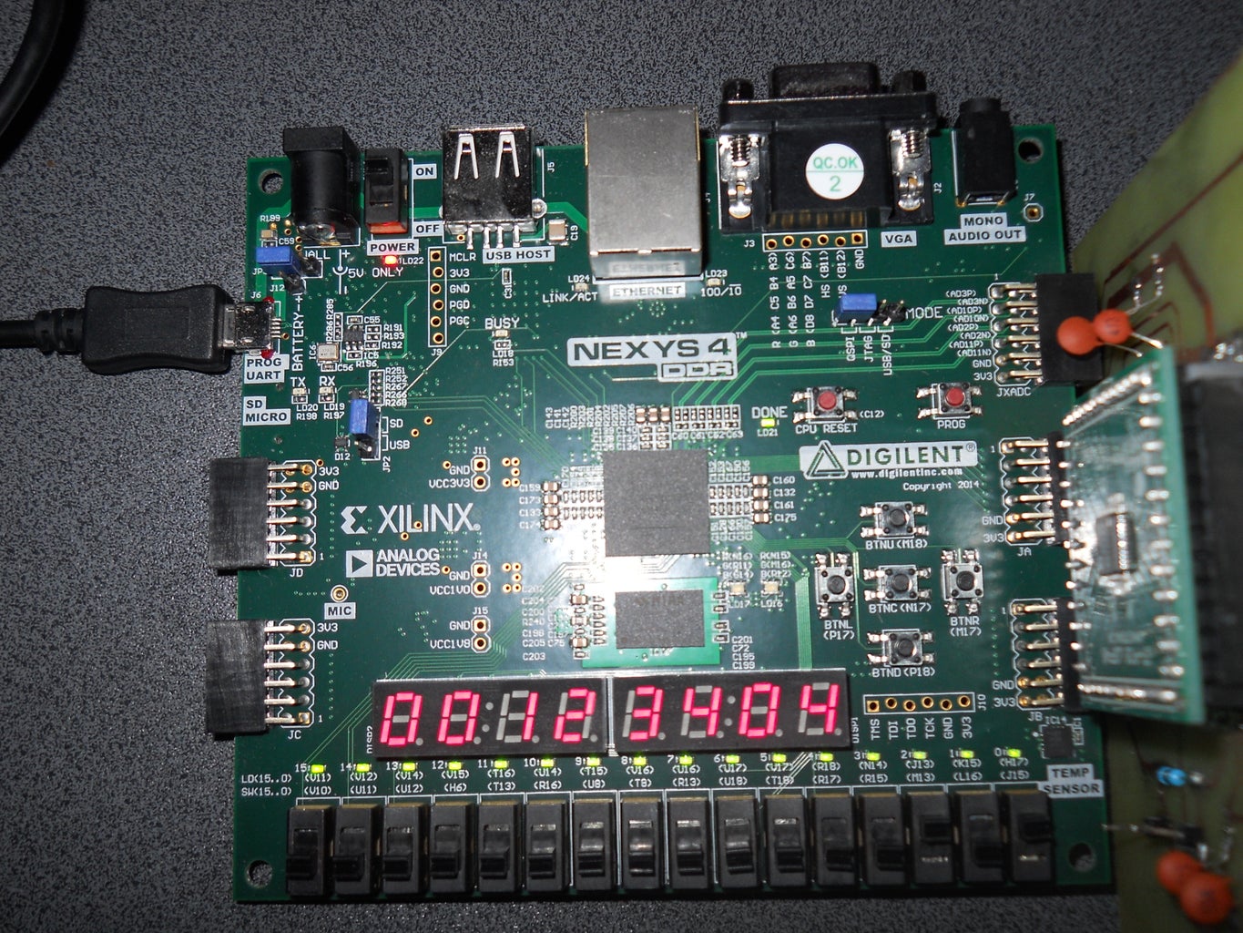
3)Digilent Nexys 4 development board
4)A high speed digital to analog converter in my case an adv7123
5)A pcb for digital to analog converter. In my case is an home made pcb.
6)PCB adapter LQFN48 to DIP.
7)Few resistors (1x75 ohm, 2x39 ohm, 1x510 ohm)
8)Few capacitors (4x0.1 u, 2x0.01 u) 9)Few pin headers male and female.
10)Some tools for soldering.
11)An osciloscope.
Step 2: Download and Install Vivado and Eagle
Step 3: Build Digital to Analog Module


For digital to analog converte I chose a chip from Analog Devices (adv7123). This chip is high speed digital to analog converter specialized for video application but can be used olso in radio aplication. This chip has 3 channels with 10 bits each and work up to 330 MSPS. Until now I tested just with 50 MSPS and can generate a cosine wave up to 6 MHz. I tried to generate bigger frequency but after 6 MHz cosine wave looks realy bad.
After I bought adv7123 chip and an pcb adapter for LQFN48 to dip(I used this adaptor because its hard to make a home made pcb for QFN48 pad.). After that I started to work at electonic schematic and with some help from chip datasheet and I succeed. When the electronic part worked correctly I strated to work at layout and at my pcb. When i finised the pcd I soldered all components and I tested the module. First module can generate analog signals up to 6 MHz but I want to increase frequency an probable I will build another module with better components.
You can buy a module if you find a high speed one. I did not find one.
Step 4: Develop Software


For this project I used vhd language and few ip blocks from Xilinx.
This software has two big modules.
First module is used to generate a variable frequency cosinus wave. For this oscilator I used dds compiler 6.0 from Xilinx. This ip block has a lot of option and all are describe in documentation. The input clock for this module has 50 MHz and I generate a 10 bits cosine wave with 1 Hz step. This part is already implemented and tested. Until now the dac module and oscilator module can generate correct analog signals up to 6 MHz(This frequency is a hardware limitation because for first dac module I used a normal thd resistor at dac output and after 6 MHz appears a lot of noise).
Second module uses the cos wave and some binary data from micro sd card to modulate these data. This part is not implemented yet.


