

Introduction: Raspberry Pi 3: RGB LED Color Effect With PWM


Hello everyone! This is going to be my first instructable and I hope you will enjoy it. :)
In this instructable, I am going to explain how to light and RGB LED with ANY kind of color do you want. I have searched a lot for just PWM usage and for a while I couldn't find anything but complicated answers. But after a while with a single, basic command everything was solved.
If you are a beginner in RPi and if you are crazy about LEDs like me, you will love this project. It is easy and educative.
So let's start!
Step 1: Obtaining the Components


What do you need:
Raspberry Pi 3 (it is not a different thing if the model is different)
RGB LED cathode or anode
1 x 100 ohm and 2 x 150 ohm resistors
Micro USB cable 2.5 A, 5 V USB Power Supply (For RPi 3 it requires 2.5 A at most, but for the older versions 2 A will be enough)
SD Card
Breadboard
Cables or Jumpers -> for this case, I would recommend female-male jumpers
Step 2: Let's Start With Hardware


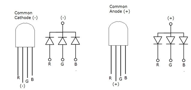

First things first, let's start with the hardware. For the hardware, you have to be sure which RGB LED are you using: cathode or anode? For that, you can basicaly test by yourself or ask your provider. For testing, just connect cables to ground and 3.3V pin and connect ground to long leg of the RGB LED and 3.3 V to any other leg. If it lights, then your RGB LED is a cathode RGB LED, if it is not working it is a anode RGB LED.
In the end, both type are LEDs and they just have a slight difference. With common cathode LED, you have to connect the long leg the ground (6th, 9th, 14th, 20th, 25th, 30th, 34th and 39th pins of RPi 3) the and with the anode LED you have to connect it to 5 V (2nd or the 4th pin of RPi 3). If you are using another version the only thing that you have to do is opening the "pin list" of your RPi model and check the 5 V pin of your RPi.
For Red, Green and Blue legs, I have chosen 20th, 21st and 22nd pins of RPi 3.
You should connect rgb led's green pin to GPIO 20, red pin to GPIO 21, blue pin to GPIO 22 but not directly, as you can see from the schematics also you have to connect the resistors -for Red 100 ohm, for green and blue 150 ohm- Then, connect the GND from RPi directly to the long leg of RGB LED if you are using common cathode. Otherwise connect 5 V instead of GND. You can also use different pins but I chose these for the software.
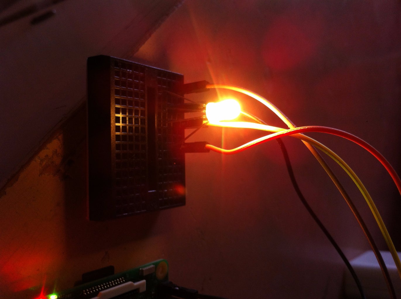
After connecting the power for the RPi 3, now your hardware part is done :)
In my pictures as you can see, I didn't use any resistors, that is because I am currently using common anode RGB LED and I have directly connected the long leg to 3.3V.
Step 3: Going on With Software
In my RPi 3, I am using Raspbian as operating system. In my opinion, it is the easiest operating system to find sources and the easiest one to learn. If you haven't uploaded yet, you can find the latest version and guidelines how to upload it to your RPi from the link above.
https://www.raspberrypi.org/downloads/raspbian/
In this instructables, I prefered to used Python to program RPi. It is an easy language to read and write and perfect for beginners, including me :)
For coding with Python, I prefer to use terminal for programming. You can also use Python 3 or Python 2 programs. But from the terminal, I find it more practical. I would love to discuss in comments if you have another opinions :)
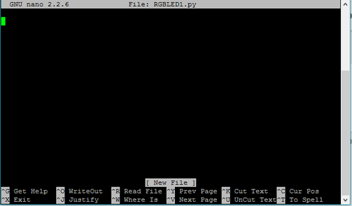
To start programming, you should open your terminal screen and type
nano rgbled.py
This command will create a new python file for your RGB LED. You can also name it whatever you want, I chose this name to distinguish it from the other programs.
You will see a blank page, for coding. Now, this is the part that you will start coding Python.
Here is the code, this code is used for cathode RGB LED because it is more common and easy to use, but I will leave comments for anode RGB LED, also I added the Python file if you can not start the program with the code, you can use that one too:
#defining the RPi's pins as Input / Output
import RPi.GPIO as GPIO
#importing the library for delaying command.
import time
#used for GPIO numbering
GPIO.setmode(GPIO.BCM)
#closing the warnings when you are compiling the code GPIO.setwarnings(False)
RUNNING = True
#defining the pins
green = 20
red = 21
blue = 22
#defining the pins as output
GPIO.setup(red, GPIO.OUT)
GPIO.setup(green, GPIO.OUT)
GPIO.setup(blue, GPIO.OUT)
#choosing a frequency for pwm
Freq = 100
#defining the pins that are going to be used with PWM
RED = GPIO.PWM(red, Freq)
GREEN = GPIO.PWM(green, Freq)
BLUE = GPIO.PWM(blue, Freq)
try:
#we are starting with the loop
while RUNNING:
#lighting up the pins. 100 means giving 100% to the pin
RED.start(100)
GREEN.start(1)
BLUE.start(1)
#For anode RGB LED users, if you want to start with RED too the only thing to be done is defining RED as one and GREEN and BLUE as 100.
for x in range(1,101):
#for changing the width of PWM, this command is used
GREEN.ChangeDutyCycle(x)
#for anode LED users, just change x with 101-x
#and for delay time.sleep is used. You can chance the duration of the colors with changing the time from here
time.sleep(0.05)
for x in range(1,101):
RED.ChangeDutyCycle(101-x)
time.sleep(0.025)
for x in range(1,101)
GREEN.ChangeDutyCycle(101-x)
BLUE.ChangeDutyCycle(x)
time.sleep(0.025)
for x in range(1,101):
RED.ChangeDutyCycle(x)
time.sleep(0.025)
except KeyboardInterrupt:
#the purpose of this part is, when you interrupt the code, it will stop the while loop and turn off the pins, which means your LED won't light anymore
RUNNING = False
GPIO.cleanup()

Step 4: Run the Code

You are done with writing the code. Now press CTRL+X to exit the code and press Y to save your code.
You have a Python code now and you need to run it.
For running a python code, you need to type into terminal:
sudo python RGBLED.py // or type in the name of your file instead of RGBLED
Congratulations if you could make until here without problems!
This is just for one RGB LED and just for seeing the colors that you can obtain. You can always improve the code and make something more and different with colors.
I hope you liked and enjoyed my instructable. I wish to write more about what I learn and share my projects in future.
See you in other instructables!


