Introduction: Raspberry Pi Classroom Arcade: Guide for Teachers & Students

Create your very own classroom arcade with a Raspberry Pi, a set of controllers, and a few other items you can find around your classroom/school. This project details how a class of middle school students, with diverse talents and interests, can build a personalized arcade. Whether your students prefer art, electronics, programming, or building things - there is something for everyone. My Computer Science class of 27 students at Norris Middle School in Omaha, NE completed this over three, 90 minute blocks near the end of the 2023 school year.
Steps
- Gather your materials and assign groups
- Load the Recalbox operating system onto your Raspberry Pi.
- Modify your table/desk to house the components for your arcade.
- Design and 3D print the controller components.
- Connect the buttons and joysticks to the printed components.
- Design artwork for the controllers and box.
- Assemble all your parts.
- Turn on the Pi and Monitor and have fun!
Supplies


Materials
- Monitor or TV with HDMI connection (19” or greater, preferred)
- Raspberry Pi 3B+ or greater
- Micro SD card of 8gb or higher
- 5V power supply (2.5 amp or greater)
- Joysticks and buttons with USB hookup
- Small student desk, table, or TV tray
- 3d printer
- Two 2x4s (8ft)
- 2 inch deck screws (approximately 16)
- 1 inch screws (approximately 15)
- Sand paper
Optional Add Ons
- Speakers
- Particle board or plywood (for enclosure)
- Clear Poly-carbonate sheets
- Keyboard
Step 1: Gather Materials & Set-up Groups


Step 1a (Materials): There are tons of variations to the design we used, but at a minimum, you will need:
• A Raspberry Pi 3b+ or higher ($35)
• Set of joysticks and buttons (available on Amazon for $40-$60). We use a set of two controllers for this project, but it could be expanded to a set of 4 controllers.
• Mid-size computer monitor or TV. We used a 24 inch display that was in our tech closet and no longer in use. Ask around to see if someone has an unused monitor or you can purchase one online for <$20.
• A table or desk on which to build the arcade. A classroom desk would work perfectly for this. We used a small table that formerly housed a sink assembly for our project. With the sink removed, we had a convenient hole to drop our wires and cords.
---------------------
Step 1b (Work Groups): Organize and assign students to complete a specific component of the project based on their talents and interests. On day 1, we outlined the entire project and assigned groups. In subsequent class periods, we reviewed the goal and instructions for each group and students got to work. I worked with groups as needed and monitored progress during the work times. Students completed journal entries to document their progress each day.
Note: Students already had exposure to Tinkercad and Canva before we started the project. The Pi and Woodworking groups needed the most support.
A) Pi Group (2-4 students): Will image and test the Raspberry Pi & load ROMs for the arcade.
B) 3d Design Group (4-6 students): Designs the button and joystick assemblies in Tinkercad
C) Woodworking Group (4-6 students): Measure, cut, and assemble the platform for the monitor and joysticks.
D) Wiring Group (2-4 students): Unbox and wire the joystick and button assemblies
E) Arcade Art Group (4-8 students): Design art for the arcade and button assemblies
F) Miscellaneous Group (1-2 students): Assist teacher with cleanup, documenting the project through pictures/videos, and finding supplies.
Step 2: Preparing the Raspberry Pi


Step 2a (Raspberry Pi): Load the Recalbox OS onto the Raspberry Pi
On a PC or Mac
- Download and run the Raspberry Pi Imager program.
- Insert your SD card to your computer
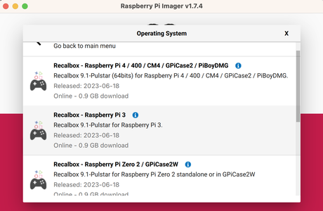
- On the RPi Imager program
- Choose OS → Select “Emulation & Game OS” → Recalbox → Select Pi type
- Storage → Select SD card
- Write → This takes approximately 10 minutes, depending on your computer
On the RPi
- Insert formatted SD card with RecalBox into Pi, then connect keyboard, monitor, and power supply (Initial boot takes 2-5 minutes)
- Use the keyboard to modify the preferences, add Wi-Fi, set controllers, and more
- “Enter” key will get you to Preferences from the home screen or go back a screen
- Arrow keys to move through options
- “A” key will allow you to select an option
At this point, your Pi is ready for gaming. The Recalbox comes with a number of games across all the systems with which students can experiment. They can use the keyboard to control (not recommended) or bring their own controller to test. Recalbox can play games from early Atari through N64. The built in selection is limited and students will need to add their own ROMs for additional game play. Students can also create their own games, playable on the system, at Makecode.com.
Step 2b (Loading Games):Use the web console or a USB stick to load games
- On a Mac, PC, tablet, or phone go into the Recalbox web console
- Make sure the RPi is powered on and connected to Ethernet or Wifi. On a separate browser (not the RPi) navigate to:
- Windows: http://recalbox/
- Mac (Safari): http://recalbox.local/
- Alternatively (any system): Go to “Preferences” on the RPi, find the IP address and type this into the browser (example: 10.8.4.45)
- You get to a console where you can adjust configurations and add games
- Navigate to the “ROMs” and locate the folder of the game system for which you have a ROM*
- Click the red “Stop ES” button before adding any ROMs
- Click “Upload ROMs” and drag and drop the ROM file to the window
- Click the green “Start ES” button and any new games you’ve added will be ready to play
- ROMS can be loaded to a USB stick & plugged into the Pi. More information on loading games via USB can be found here.
Teaching Tips
- Adding games via the web console requires a network connected RPi, but some schools may not allow a Pi to be connected on their network. Students can still load games via USB stick. The RPi and Recalbox do not need an Internet connection to run games.
- My district would not allow the RPi Imager program on student or staff devices so I loaded Recalbox on the SD card with my personal device, then gave the formatted SD card to the students. They got it up and running fairly quickly, so I then had them research how to load games via USB stick.
- If your system won't boot or has trouble, just reload Recalbox on the SD card and it will run like new.
*ROMs are the files that run games. Please follow all laws when acquiring and using ROMs.
Step 3: Woodwork for Arcade Controllers


Woodworking Group: Use the 2x4s and screws to construct a square (or rectangle) piece with a T-cross beam through the middle that will support the controllers, monitor, and speakers.
The size of your table will determine how big to make the wooden rectangle, but the button assemblies (see step 4) require that you have at least 20 inches of horizontal space between the edges of the boards. For our assembly, students cut and assembled a 20in x 20in square (inner measurements) which spanned the width of our table and later added a “T” block to fit our controller assembly and the monitor base..
Connect all components with the 2 inch deck screws at each junction (2 screws per junction).
Teaching Tips
- Students need to be shown how to measure and mark the cut lines on the 2x4. I had multiple students measure and mark on opposite sides of the board, then verified before they cut.
- We used a hand saw for safety purposes. Since there were six students in the woodworking group, I typically had three groups of two who would measure and cut a leg of the square so they each had an opportunity to cut. I demonstrated the measuring and cutting process for the first board, then let them loose.
While one group cuts, I have the other groups sand the edges of the cut boards and work to get the cuts as straight as possible. Cuts with the handsaw can get a bit janky, but the sandpaper helps and keeps all hands busy.
Step 4: 3d Design & Print Controller Housings


3d Design Group: Create the button and joystick housing on Tinkercad. This is a relatively easy item for students to design in Tinkercad. The only tricky part is getting the holes correctly sized. If you prefer, you can use the template one of my students designed here (file attached below) and modify as needed. Here are the specs:
- Create a 8 x 10.34 x .25 rectangle
- Insert 8, circular holes with a diameter of 1.1 inches
- Standard buttons are 1 inch in diameter, so adding a little extra allows them to slide into the hole
- We used 8 buttons, but adding a 9th may be advantageous
- (Optional): The student design has an open rectangle, originally designed for the joystick housing, but it did not fit. This can be adjusted or eliminated. We later covered the opening with instructions for the controller.
Teaching Tips
- I use the educator version of Tinkercad, which allows me to create classes, review, modify, and download all student designs in my teacher dashboard. It also allows me to assign templates that students can modify and make simple adjustments to before I send it to print.
- If the button holes end up a bit too small, you can use sandpaper or a Dremel to file them down so the buttons fit. The first iteration of the button housing designed by the students was too tight, so they Dremeled it, then widened the holes on the second print.
We ended up drilling pilot holes through the printed plastic to attach the joystick assembly. This gave us flexibility, but additional work on the 3d model could make this unnecessary.

Step 5: Wire the Buttons & Joystick


Wiring Group: Wire the buttons and joysticks to the USB interface board.
This is a straightforward process, however it is important that the wiring is identical for all controllers. If button A goes to Port 1 on the first controller, the second controller should be wired the same. It is easy to mix up buttons when attaching them to the 3d printed housings.
Teaching Tips
- This station is accessible to students of all abilities, but requires some organization.
- Have students label each wire (Port 1 = Button A, Port 2 = Button B…) so that each wire gets connected to the correct button on final assembly.
- The wiring is quick, but the unboxing and organization takes additional time.
- Plug in the USB interface controller to the RPi
Step 6: Design Arcade Artwork


Design Group: Students use Canva, Adobe Express, or another tool to design art that can be used on the arcade.
This group of students can use a variety of tools to create art for the controllers, sides of the arcade box, or directions for use. For our project, several students created art based on classic games and one student created a guide for our controllers. We did not finish the enclosure for our arcade, but did print off the student design for the button configuration and used it on the arcade.
Step 7: Assemble All Parts


Assembly: Since we were in the last week of school, I (hastily) assembled the student created parts so we would have time to play. In the coming year, we will probably 3d print some components to make it a little smoother and add an enclosure that will be covered with student artwork.
Teacher Notes
• Double check that the button ports line up with the same buttons on both controllers (see step 5).
• I anchored the RPi with a premade plastic piece I had laying around, but a 3d part could easily be fashioned for this.
• Make sure you have a 5V power supply of 2.5amps or greater to power all components. Initially, we used a 2amp power block and the RPi would not always start up when the controllers were connected.
Step 8: Start It Up & Play
