

Introduction: Raspberry Pi Cluster Case
The main idea behind this design was to create a cluster case for Raspberry Pi, minimizing overall downtime if one fails; swap one out, without having to take down the entire cluster. Some designs locked the Raspberry Pi base by the side, requiring the full dismantle of the case to swap one Raspberry Pi from the case itself. In this design, each Raspberry Pi has its own tray, USB power cable, and ethernet cable, independent of the other Raspberry Pi in the cluster.
The 120mm fan airflow is funneled directly through the Raspberry Pi, with heatsinks oriented to allow airflow between the fins. Additionally, the 120mm fan does not produce enough airflow on 5v power (provided by Raspberry Pi or USB adapter); usually runs at 12v from PC connection. I split the USB adapter cable, and placed a buck converter to amplify 5v to 12v, providing the necessary power for the full RPM of the fan. The hole in the front right tower allows for 3- and 4-pin connectors.
The USB power hub is mounted underneath the base, with USB-C at the rear. This orientation allows for a USB-A port near the front, for the buck converter to use. In my build, there is a Raspberry Pi 4B, which uses USB-C for power. I placed it at the top-most slot, as this helps with cable management, and doing a rack order of 1-4, from bottom to top. Depending on which power hub you use, this may or may not be ideal placement, or of use.
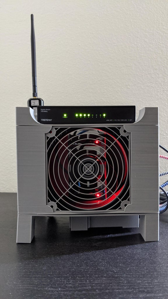
The top houses the TRENDnet 8-port unmanaged switch, which can fit snugly with the rubber pads attached. The spacing was made for that switch, which may or may not be suitable for other similar switches.
Each Raspberry Pi has its own use:
- Monitoring
- Nagios
- Monit
- Grafana
- Pi-hole
- Kali Linux (armhf)
- Public Services
- OpenVPN
- Pi-hole
The Pi-hole was in production, and appears empty from the red tray. The others were new Raspberry Pi without services on them, other than SSH for headless setup. There are caps I printed after doing the build, and are not pictured. One of the caps (rear left) has a holder for a WiFi USB adapter, that I connect to Kali.
Supplies
All links go to Amazon, for the exact item I purchased
- Raspberry Pi (I used 3B+ and 4B)
- microSD Cards
- Heatsinks for the Raspberry Pi
- TRENDnet 8-port Unmanaged Switch
- 1-foot cat6 Ethernet Cable
- Anker USB Power Hub
- USB Power Cables
- 120mm Fan
- ARCTIC P12 1050RPM (3-pin)
- Noctua NF-P12 1300RPM (4-pin)
- 3- and 4-pin Fan-to-USB adapter
- Buck Converter
- Knurled Threaded Inserts
- M5x10x7 (mid-section)
- M2.5 with Heat Set Insert Tip (Raspberry Pi trays)
- Weller SP40NUS Soldering Iron (for insert tip)
- Screws
- M5x25 (top/bottom to mid-section)
- M2.5x8 (Raspberry Pi to tray)
OPTIONAL
- Needle Nose Pliers (holding heated inserts)
- I used straight pliers on the midsection inserts, and curved pliers on the tray inserts. The curved pliers let me grab it from the top ring, and push down simultaneously.
Step 1: Print the Parts


The STLs can be found on my Thingiverse page, with the same project name: Raspberry Pi Cluster Case
Each printer has its own configuration, and slicer with its settings. I printed mine on Ender-3 Pro, with 0.2mm height, 20% infill, using standard 1.75mm grey PLA filament from Hatchbox. Infill can go as low as 15%, but these are mostly thin walls (2mm thick).
NOTE: Due to melting from heated knurled inserts, print with at least 3 walls on shells.
Print the base upside-down (legs up) to minimize supports, which are only needed for the USB power hub enclosure. In my original print (seen in the pictures), the base did not have the inner arcs. I found that while it still works, it felt a bit flimsy; sturdier once screwed into place.
Any 120mm fan grill will work, as long as it's printed 1mm thick. Customizable Fan Grill Covers by mightynozzble is a good place to start, with various designs.
These are the results per STL item, per Cura 4.7.1, using my aforementioned settings
- USB Enclosure Cover
- filament: 3.24m
- time: 1:15
- Front Right Tower Door
- filament: 2.09m
- time: 0:45
- Caps (8 total, for top and base)
- filament: 0.93m
- time: 0:20
- Left Door
- filament: 7.39m
- time: 2:25
- Raspberry Pi Trays (4 of these)
- filament: 6.16m
- time: 2:02
- Top
- filament: 39.88m
- time: 12:47
- Base
- filament: 50.27m
- time: 16:27
- Midsection
- filament: 118.10m
- time: 42:46 (1 day, 18 hours, 46 minutes)
The alternative is to not have a left door, and/or print a cap with the WiFi USB adapter
- Midsection without Door
- filament: 114.17m
- time: 40:32 (1 day, 16 hours, 32 minutes)
- Cap with WiFi USB Adapter
- filament: 4.77m
- time: 1:45
Step 2: Verify the Prints Work


Start by cleaning all of the support floors and ceilings to avoid obstructions. Some of the basic things to ensure the prints were successful
- Clips for the buck converter and its door are not flimsy or drooping
- Tray arm should have some play without snapping
- Trays slide in without rubbing the walls
- Trays can lock once fully inserted, and disengage with a pull
- Trays have space in the groove, without scraping
- Fan and grill fit in its slot
- Fan connector fits through the hole
- Screws fit in the hole with minimal resistance
- Holes line up between the mid-section and the top/bottom
- Left door can swing in the hinges (if printed)
- with top on, ensure it can (dis)engage the locking pin without coming out
- when closed, the locking pin should rub the opening on the back of the door
- Switch fits into the enclosure
- rear insert, side with smaller fillet
- USB power enclosure is snug, or with minimal play
- Cover should slide in, and snap into place
Stacked and somewhat assembled, it shouldn't have anything needing force to fit together. The fan and grill should be snug, but not tight and about to break the corner clips.
Step 3: Adding Knurled Threaded Inserts


The heat insert isn't required. Although it helps, the insert can get stuck, and melt more of the plastic than intended. For this reason, I used needle nose pliers to heat the threaded inserts, and push them into place.
The M2.5 will heat up sufficiently within 2-3 seconds, and can be inserted with the curved pliers. The M5 insert will need more time to heat. It's best to heat what will be the outer ring first, for about 10 seconds, then apply heat to the ring entering the hole for about 15-20 seconds. This will allow the insert to push through the plastic walls, before it cools and grabs onto the walls.
NOTE: When inserting the M2.5 knurled inserts, it may slightly warp the riser with the hole. While it's still setting, the pliers can shape the plastic to grab onto the knurls, which is helpful with the holes closest to the tray's arm.
If not using the heat insert, there are other options:
- Soldering iron
- Heat gun
- Blow dryer
- Lighter
Screw the Raspberry Pi onto a tray (USB and NIC facing the tray's lip), and insert it into the mid-section, ensuring it fits. Take note of the direction of the heatsinks, as that will allow airflow through the Raspberry Pi.
Step 4: Buck Converter Output: 5v to 12v


TOOLS
- Soldering iron
- 120mm fan
- Buck converter (step-down converter)
- 3- or 4-pin to USB adapter (whichever fits the fan)
- Voltmeter or Multimeter
- Wire Strippers or Utility Knife
Most 120mm fans will have either 3- or 4-pin connectors. The USB adapter will only run 2 cables: power (red) and ground (black). These will be soldered to the respective positive (+/red) and negative (-/black) holes on the buck converter.
NOTE: the USB cable will connect to the IN side, and the fan connector will connect to the OUT side. All buck converters have IN/OUT markings, along with positive and negative, but some will also have an arrow, pointing from IN to OUT (mine is underneath).
The USB adapter will only provide 5v, and the buck converter will provide the 12v needed for full fan efficiency. Any buck converter that can input at least 3v and output to at least 5v should suffice for pushing 5v to 12v.
Any voltmeter/multimeter with up to 20v setting will suffice for testing the output voltage of the buck converter.
STEPS
PREP: have the soldering iron warming up
- Cut the USB adapter for the fan
- Measure twice, cut once
- Half way worked for me, but you'll need less for the fan, than USB
- Strip away the sheath to expose the red/black cables
- Strip the sheath around those cables to expose the conductor cable
- Insert the conductor cable (twist the strands) through the top
- Doesn't matter which, as long as it goes into the correct hole:
- Black USB to IN-
- Red USB to IN+
- Black fan connector to OUT-
- Red fan connector to OUT+
- Doesn't matter which, as long as it goes into the correct hole:
- Solder each pin from behind
NOTE: As this will sit flush against a wall, trimming or sanding down the excess is acceptable, as long as the solder maintains a connection between the board and cables.
VOLTAGE SETTING
PREP: connect the fan to the buck converter, and USB power supply
- Using the voltmeter/multimeter, set it to read more than 12v (usually 20v setting)
- Place the leads on the respective OUT cable (black to black, red to red)
- There is a screw (usually brass) atop the buck converter
- Turn counter-clockwise to lower voltage output
- Turn clockwise to increase voltage output
- Once at 12v, check the fan to ensure it's operating successfully
NOTE: determine the airflow direction, as you'll want the airflow to go into, and through the Raspberry Pi Cluster Case.
Disconnect the fan, and unplug from the USB power supply. This is ready to go into the front-right tower. Connect the fan to the buck converter OUT, and insert the USB from IN through the provided hole. Slide into the inner clips, then press down to lock into place with the outer clips. Connect the buck converter to the USB-A port, and ensure it works. Close the tower with the door.
USB Cable Management
In this build, the Raspberry Pi 4B uses USB-C, while the Raspberry Pi 3B+ use microUSB (with USB-A cable). The fan uses USB-A, and for this reason, the USB-C will be closest to the rear, ensuring a close port to use. The USB power hub has 4 USB-A ports, and 1 USB-C port, which I have going from bottom to top:
USB-A-1 to buck converter
USB-A-2 to tray 1 (bottom)
USB-A-3 to tray 2
USB-A-4 to tray 3
USB-C-1 to tray 4 (top)
Step 5: Wire It Up

Depending how you setup your Raspberry Pi, these should be good to go. This unmanaged switch can detect which port provides Internet, and routes accordingly. For cable management, I networked from bottom to top, identical to the USB cables:
Switch port 1 - tray 1 (bottom)
Switch port 2 - tray 2
Switch port 3 - tray 3
Switch port 4 - tray 4 (top)
Switch port 8 - router for Internet
With power to the switch and USB power hub, the switch should be providing Internet access, to all the powered up Raspberry Pi, and cooled with the running fan.


