

Introduction: Sampling Rate/Aliasing Instructable

I wish to create an educational project that demonstrates aliasing (and sample rates) and is intended to be placed on a website as a resource for students who are learning about aliasing.
Step 1: Ciruit Layout


Arduino
The Arduino is the base of the circuit; supporting the servo motor (with mounted encoder wheel), and the positioned hall effect sensor.
-Encoder wheel:The encoder wheel's purpose is to suspend a magnet that rotates in a circular path, hovering over a positioned hall effect sensor.
-Sensor setup: The hall effect senor is placed below the rotation path of the magnet, its purpose is to track the passing of the magnet with various rotation speeds and data collection rates.
-----------------------------------------------------------------------------------------------------------
Sub-Steps:
- Obtain materials:
- Arduino (+ bread board), wires, encoder wheel, magnet, hall effect sensor, servo motor, Matlab application, Arduino application.
- Cut out encoder wheel, mount onto servo, push in magnet into slot.
- Attach hall effect senor underneath path of magnet (wire extensions of sensor may be required).
- Build circuit.
Step 2: Arduino Code

Method of data collection
- The Arduino code uses [Line 41] to collect information, through the 'Analog In' A0 port, from the hall effect sensor.
Method of serial data transmission
- [Line 43] Displays into the serial monitor a variable 'timer' that implements the function 'millis()' to keep a running timer in milliseconds for the duration of the program.
- [Line 45] Displays into the serial monitor a variable 'hallsensor' that implements 'analogRead' to obtain information from the hall effect senor as the program is being ran.
Purpose of the delay() parameter
- The purpose of the delay() parameter is to vary the response time of data collection that is received from the hall effect sensor.
-----------------------------------------------------------------------------------------------------------
Sub-Steps:
- Input Arduino code in Arduino application.
Step 3: Matlab Code (HallRT File)


-Method of data receipt - [Figure 3: Line 77]
- Obtaining data from the ArduinoStep
-----------------------------------------------------------------------------------------------------------
Sub-Steps:
- Input Matlab code is above figures, save in HallRT file.
Step 4: Matlab Code (thresh_analyze)


Method of counting peaks[Figure 2: Lines 45-53]
- The usage of the flag in this Matlab code is so that once the for loop stumbles onto an 'aRval' that is larger than the pre-set 'thresh' value count will increase by one, the peak will be marked by an asterisks, and the if-statement [Line 45-50] will break because flag = 1. The second if-statement with a flag [Line 51-53] indicates that once the peak is met and the values begin to decline around the peak, then flag = 0 and the for loop continues to search for more peaks.
- Parameters/Necessary Values:
- 'aRval': The collected data from a trial run.
- 'thresh': A chosen value to indicate anything above it in aRval as a peak.
-----------------------------------------------------------------------------------------------------------
Sub-Steps:
- Create a second Matlab file "thresh_analyze".
Step 5: Trial 1: No Aliasing
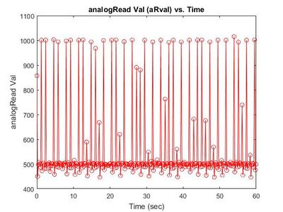

Figure 1: Data Trial @ Delay 200
Figure 2: Thresh Analyzed Data
-Delay Parameter: 200
-Peaks:
- Count = 45
-Number of Revolutions per minute:
- 45 Revolutions/Minute
-----------------------------------------------------------------------------------------------------------
Sub-Steps:
- Connect the Arduino to your laptop.
- Set the delay in the Arduino code to "200". Press Upload (in the top left corner of the application).
- Go to your Matlab file HallRT [Line 37] and change the variable 'delayTime' to 200.
- Run the HallRT program.
- Save the Matlab file under "delay_200". (Save Figure)
- Load the delay_200.mat file.
- Run the thresh_analyze program. (Save Figure)
Step 6: Trial 2: Aliasing of Sensor (i)


Figure 1: Data Trial @ Delay 50
Figure 2: Thresh Analyzed Data
-Delay Parameter: 50
-Peaks:
- Count = 52
-Number of Revolutions per minute:
- 52 Revolutions/Minute
-----------------------------------------------------------------------------------------------------------
Sub-Steps:
- Connect the Arduino to your laptop.
- Set the delay in the Arduino code to "50". Press Upload (in the top left corner of the application).
Go to your Matlab file HallRT [Line 37] and change the variable 'delayTime' to 50.
Run the HallRT program.
Save the Matlab file under "delay_50". (Save Figure)
Load the delay_50.mat file.
Run the thresh_analyze program. (Save Figure)
Step 7: Trial 3: Aliasing of Sensor (ii)


Figure 1: Data Trial @ Delay 100
Figure 2: Thresh Analyzed Data
-Delay Parameter: 100
-Peaks:
- Count = 54
-Number of Revolutions per minute:
- 54 Revolutions/Minute
-----------------------------------------------------------------------------------------------------------
Sub-Steps:
- Connect the Arduino to your laptop.
- Set the delay in the Arduino code to "100". Press Upload (in the top left corner of the application).'
- Go to your Matlab file HallRT [Line 37] and change the variable 'delayTime' to 100.
- Run the HallRT program.
- Save the Matlab file under "delay_100". (Save Figure)
- Load the delay_100.mat file.
- Run the thresh_analyze program. (Save Figure)
Step 8: Trial 4: Aliasing of Sensor (iii)


Figure 1: Data Trial @ Delay 300
Figure 2: Thresh Analyzed Data
-Delay Parameter: 300
-Peaks:
- Count = 32
-Number of Revolutions per minute:
- 32 Revolutions/Minute
-----------------------------------------------------------------------------------------------------------
Sub-Steps:
- Connect the Arduino to your laptop.
- Set the delay in the Arduino code to "300". Press Upload (in the top left corner of the application).
- Go to your Matlab file HallRT [Line 37] and change the variable 'delayTime' to 300.
- Run the HallRT program.
- Save the Matlab file under "delay_300". (Save Figure)
- Load the delay_300.mat file.
- Run the thresh_analyze program. (Save Figure)


