

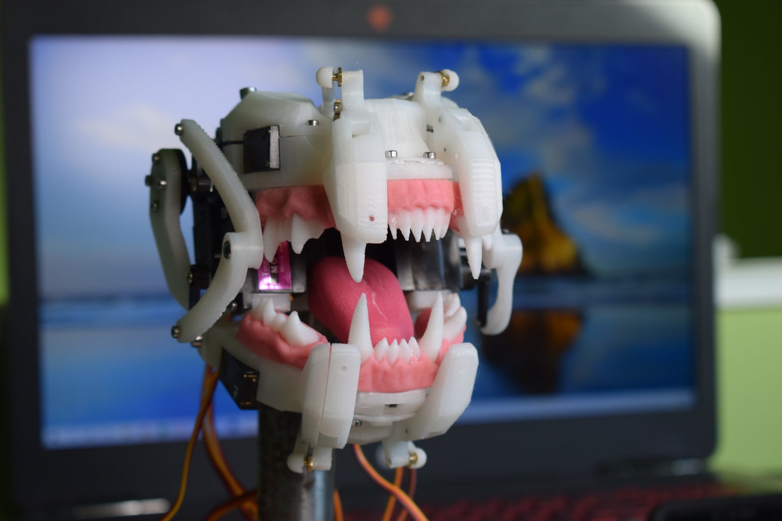
Introduction: Simple Animatronic Mouth Using 3D Printing, Arduino and Python


Inspired by Disney's Shaman Animatronic, as well as 3D printed designs by WillettFX and TheDutchEdition, I recently decided to build a 3D printed animatronic mouth design. Although the mechanics of the design are very simplified compared to the other projects I mentioned, I wanted to add a tongue to my design as it's a big component in realistic looking lip-synchronisation. Also, I developed a few different control methods including a program which takes a sentence as an input and converts it into a sequence of visemes (mouth-positions), and another which uses real-time input from a microphone.
This project is a nice introduction to animatronic mouths, but there's a lot of room for better control methods and more complex mechanics. I can't wait to see what the community can come up with!
Attachments

Supplies
Mechanics
- 7x MG90s Micro Servo (2x https://amzn.to/2W3pnUJ)
- 2x MG996R Servo https://amzn.to/2SfjPFp
- Various M2 and M3 screws
- 8x M2 Servo Ball-links: https://amzn.to/2Kq8fDK
- 4x M2 short pushrod connectors (best just to get M2 screws and saw them up!)
Teeth/Tongue
- Tongue
- Super Sculpey Beige https://amzn.to/2YdCLsa
- FIMO Cherry Red https://amzn.to/3eZr8Lm
- Teeth (optional)
- FIMO Translucent White https://amzn.to/2YdoI5G
- FIMO Sahara https://amzn.to/3cYzbGt
- Pictured Gums
- Super Sculpey Beige https://amzn.to/2YdCLsa
- FIMO Cherry Red https://amzn.to/3eZr8Lm
Control
OR
- Arduino Uno: https://amzn.to/2XoMolo
- Adafruit PCA9685 16-Channel Servo Driver: https://amzn.to/2NQeNNT5.5mm
- DC panel input - https://amzn.to/2NQeNNT5.5mm
- Power supply (5A in this case to allow many servos to be driven) - https://amzn.to/2NQeNNT5.5mm
- Potentiometer - https://amzn.to/2NQeNNT5.5mm
Step 1: Creating the Teeth and Tongue


Although its possible to print the teeth, there are multiple ways you could go about making them. I was fascinated by WillettFX's methods of creating teeth for animatronics using real dentistry techniques, but struggling to find the materials needed I opted for a cheaper solution using polymer clay. My first set of teeth was made by simply sculpting
To create the tongue, firstly print out the tongue base, front tongue linkage and rear tongue linkage, and assemble these parts as shown. These parts will be boiled briefly, which often isn’t an issue but it could cause some warping - ideally use ABS or some other high-temp filament, but the warping shouldn't be too much of a problem. Super Sculpey is very easy to sculpt especially compared with FIMO, but it is very brittle and there’s not very many colour choices. Painting is obviously an option but Sculpey is slightly translucent which is perfect for organic fleshy things and you could loose that with paint.
I mixed around 15-20% cherry red fimo with super sculpey in the final version, but my first tongue was cherry red FIMO + a little antique rose. Sculpting was just a small amount of creases and focus on the texture, which I did by pressing with fabric and lightly rolling the knurled parts of my tools against it. Be sure not to make it too thick or long – ideally print out the "tongue [No sculpting]" file and use this as a guide.
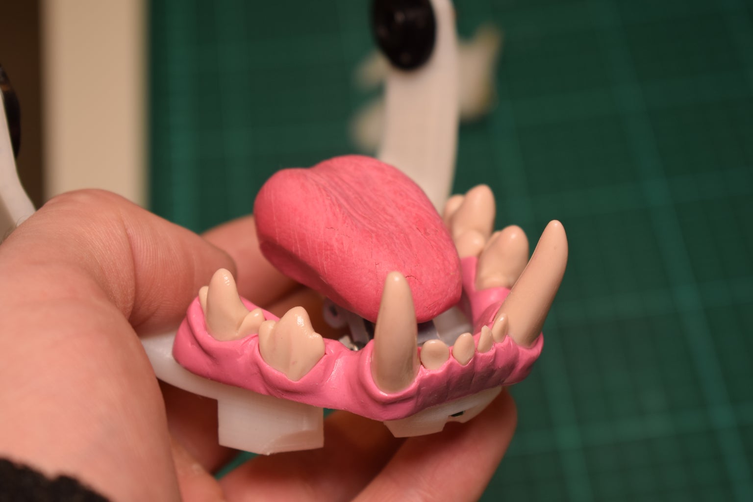
For the teeth, I tried multiple techniques. The first was to simply sculpt them - using a mixture of translucent FIMO and "sahara" in a ratio of around 7:3 I firstly sculpted all the individual teeth. These were boiled for 30 mins, then I used the top and bottom tooth base components as a base on which I sculpted the gums. If you try this method however, be careful that your gums do not protrude too far from the bases, because this could obstruct the mouth mechanism. Unfortunately I found the FIMO difficult to work with, so I was not too pleased with my result.
The best method I tried was to print out a frame with all of the teeth connencted to a base, and sculpt the gums over this frame. Initially I tried printing in ABS and acetone smoothing, but the results were quite disastrous! Unfortunately you'll have to either polish the teeth by hand, or print them in resin. Using a mixture of 95% sculpey and 5% cherry red FIMO I got a nice realistic and translucent gum colour.
Step 2: Getting and Setting Servo Positions


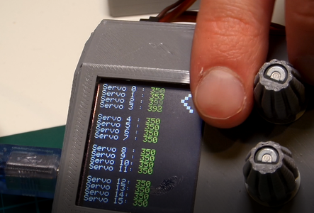
I have another instructable about a 16-channel servo tester I built. This was instrumental in assembling the mouth and finding positions of the motors in different mouth-positions. I'd recommend you build one for yourself as it has many uses beyond this particular project, but if you don't fancy it, I have an alternative.
In the download pack you should find an Arduino program called Servo_Tester_Alternative. This is a simple alternative that will allow you to control four servos at once using four potentiometers. Simply upload the code to the Arduino and wire as shown above, and you can use the program in conjunction with the Arduino IDE serial monitor to set the servo positions.
NOTE: If you are using my servo tester and you want to use it while connected to your PC serial connection (for the text-to-animation program I describe later on), its strongly advised that you disconnect the connection from the PWM driver board's V+ pin to the Vin pin of the Arduino, since the USB provides power to the Arduino.
Attachments
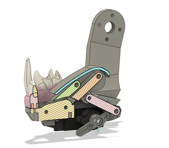
Step 3: 3D Printing and Building the Mechanism


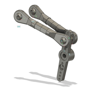


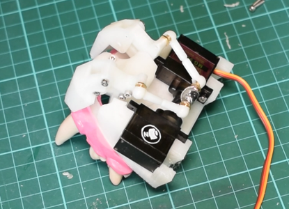


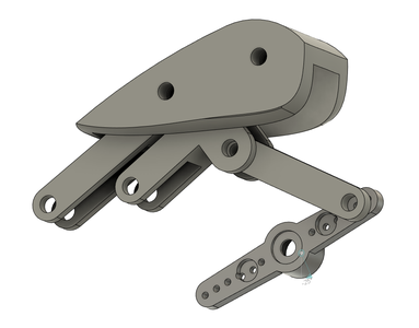


There aren't any specific requirements for the 3D printing, pretty much everything was printed at a layer height of around 0.25mm for my model, but you may want to go lower just for aesthetics! I have built-in allowances for the different types of fit amongst the screws in the model, but since there can be quite a lot of variation between the output of different 3D printers, it may be necessary to use a small drill to make some holes bigger.
When everything's printed and ready to be put together, be sure to refer closely to the diagrams and video to ensure it goes together correctly!
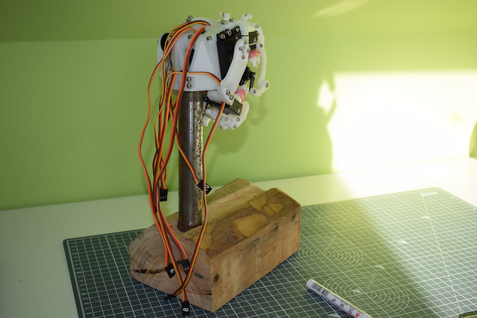
- Preparing the base
- Depending on your application, you will need a base for the mouth to attach to. Its designed to clamp on to a 1 inch or ~25mm diameter tube, so the simplest solution is just to attach a 1 inch tube to a piece of wood to make a solid base.
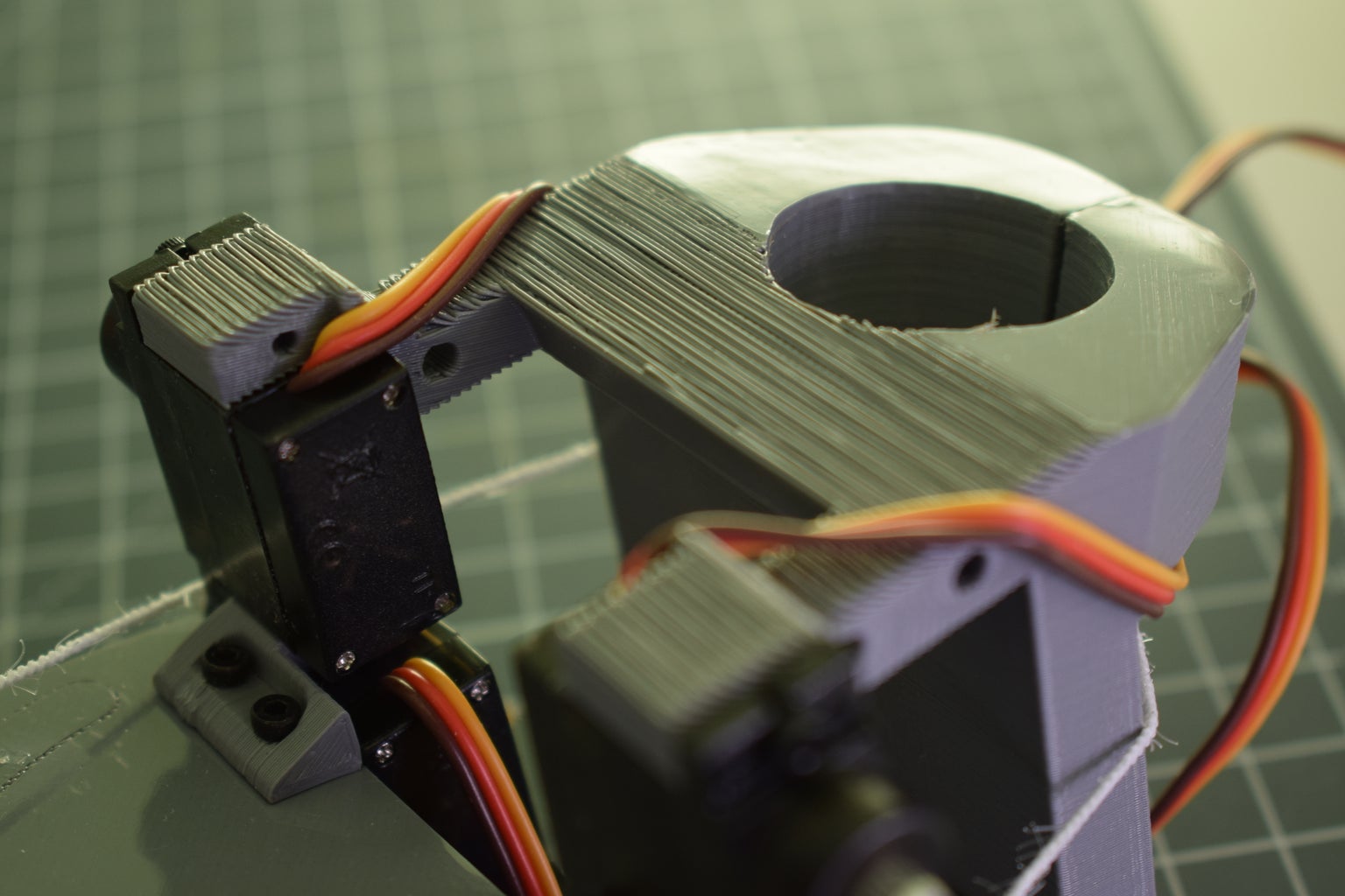
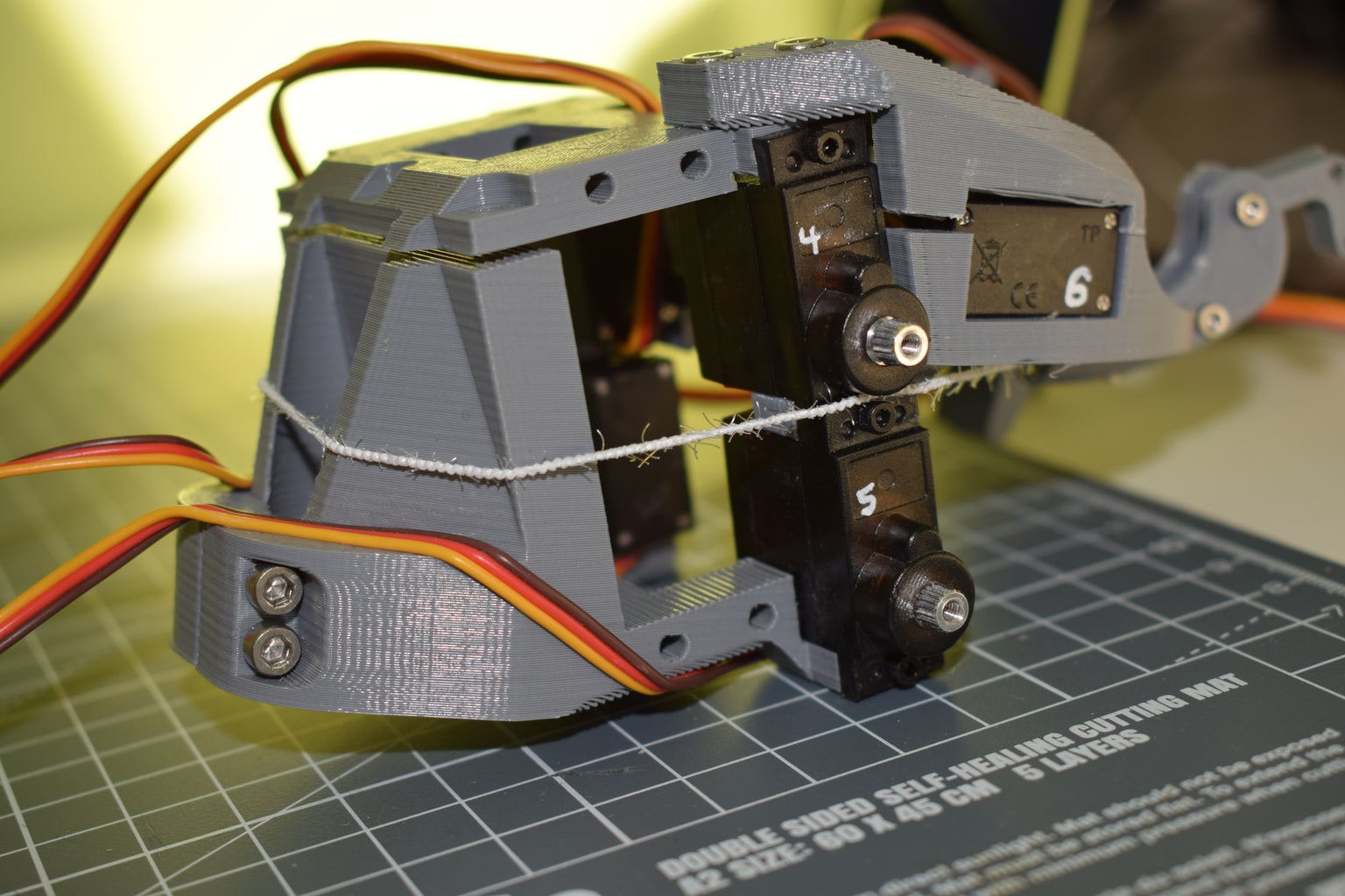
- Build the main servo block
- Starting with the two pairs of MG90s servos, use the "Top Under Bracket" component to link them together, this may be a bit fiddly and will require you to hold the two servos in position while you screw in the M2 x 8mm-12mm screw. Refer to the diagrams to make sure you have them facing the right way, and have the correct servo on top of the other.
- Set these aside and screw a pair of MG996R servos to the "Servo Block" using 4 M3 x 6mm-10mm screws, also attach the "Servo Block Top" using 3 M3 x 6mm-10mm screws, which will allow you to further secure the MG996Rs with two more M3 screws.
- Combine these three elements by screwing the MG90s' you combined in the first step to the "Servo Block" using 4 M2 x 6mm-12mm screws.
- Build the top and bottom base lip assemblies
- Build up the "Lip Teeth" components by screwing together "Lip Right Tooth 01 [and 02]" using two M2x10mm screws with a "Lip Top Linkage" and "Lip Bottom Linkage" enclosed, as shown in the diagrams. You can make an identical one of these which can be set aside and used for the bottom base later on, and two more mirror images (one for the top and bottom).
- Using a short length of M2 threaded bar (or simply an M2 screw with the head cut off), join four pairs of M2 ball-links together. Then attach a pair of the pairs to an MG90s servo horn on the third hole from the end, and make two pairs of these. I ran out of through-hole ball-links so I had to use the screw-in version, for this I have a little adaptor which serves as a servo horn but can also be screwed into
- Attach the left and right lip tooth assemblies to the "Top Piv" component as shown, and do the same for the "Bottom Piv". Also attach the ball-link assemblies you just made to the free holes on the top linkages. If you're using the through-hole ball links as pictured, you can screw into the insides, but if you're using the screw-in ball links you'll need to screw into the outsides.
- Set the servos to a pulse-width of 350 (this is roughly 90 degrees for an MG90s servo) using my servo tester, or the in-screen servo tester I have in the download pack. Then attach the servo horn such that it's perpendicular to the body of the servo. Check the images so you can be sure about the orientation! The orientation should be identical for both the top and bottom lip base assemblies.
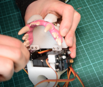
- Build the top half
- Firstly the teeth will need screwing to the top base component - the screws at the back of the teeth (the ones which have recessed holes for the bolt head) can be simply screwed in with M2 x 6mm screws. The front two screws also hold the top lip base assembly in place, so take the top lip assembly you built in the last step and screw it through the top base, into the teeth using M2 x 6mm screws.
- You can let the servo dangle as you screw the teeth in, but once they're in you can screw the servo to the top base using M2 x 6mm screws. You'll only be able to get to the rear hole, don't worry about that right now.
- You can also put in a redundant servo into the other side - I had a dead servo so I popped it in there so the assembly would be more symmetrical :).
- Use 4 M2 x 6mm screws to attach the main servo block from the first step to the top half through the "top under" brackets as shown.
- Complete the top half by screwing on the "Over Top Support" components, starting with the two M2 x 6mm screws at the front, then the four M3 x 6/10mm screws at the rear. Depending on a ton of different factors you might have difficulty screwing the M3 screws in, but just flex the whole thing until the holes line up.
- Its a good idea to use super glue to fix the wires that hang from the bottom of the top half to the clamp at the back as shown.
- Build the bottom half
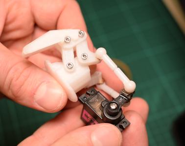
- Start by making the jaw linkages. The MG996R servos come with a circular attachment, use four M2 x 6mm screws per side to hold the jaw linkages against the servo wheels. Note that the attachment fitting on the servo wheel faces away from the linkage.
- Attach both jaw linkages to the bottom base with M3 x 5mm screws (you could probably get away with anything up to 10mm screws actually).
- Attach the tongue assembly. I recommend you start by attaching the "Tongue sLink" to the rear tongue linkage with an M2 x 8mm screw, and attach the other end to a servo horn on the third hole from the centre. Then you can screw the tongue assembly into the bottom base with two M2 x 10mm screws. Make sure it moves smoothly as it will be difficult to adjust later.
- Attach the bottom teeth with M2 x 6mm screws up through the bottom of the bottom base.
- Unlike the lips, you can reach the tongue servo to screw in the horn even after the servo has been screwed into the bottom base, which means that it's easier to calibrate the servo's position. Screw the servo in without its servo horn.
- Using my servo tester as mentioned, set the tongue servo to a pulsewidth of 340, which corresponds to the tongue in a relaxed position. Connect and screw in the servo horn such that the tongue is as far back as it can comfortably go. If you test the servo using the servo tester, it should be at its range of motion should go between 340 and 495.
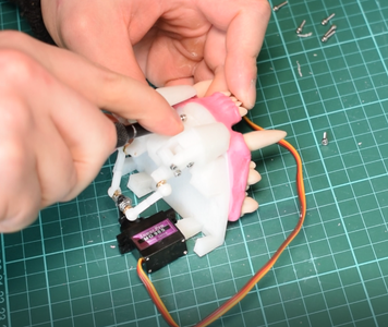
- Attach the bottom lip assembly by simply screwing in the three M2 x 6mm screws and fixing the servo in position.
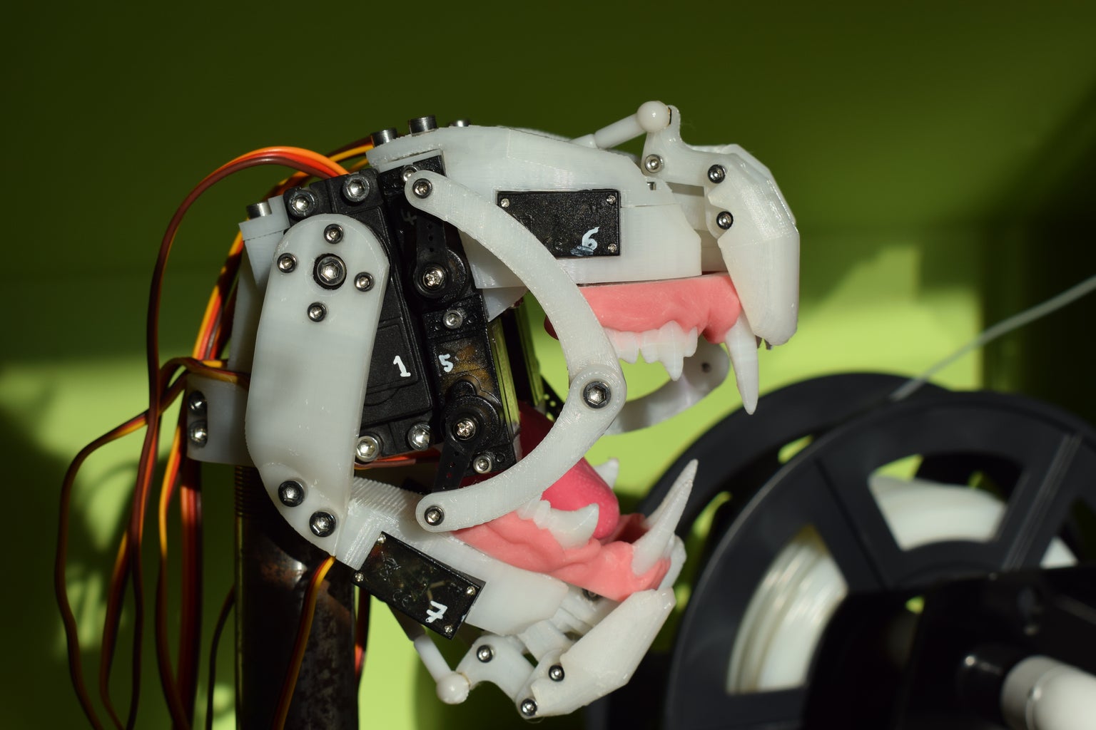
- Attaching jaw and cheeks
- Plug in the two MG996R servos to the servo tester, check the images so you know which is 0 and which is 1. Set servo 0 (the right side if looking at the mouth head-on) to 400, and servo 1 to 350 - this should be the position of the mouth with the jaw shut, so clip the jaw on to the MG996Rs in a position such that the mouth is shut. Use M3 x 5mm screws to connect the jaw to the servos.
- You can now attach the mouth to your base, using M3 x 20mm screws to form the clamp.
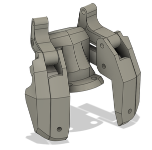
- Make up the cheek assemblies by screwing an M3 x 5mm screw through the "lower cheek" component (and into the recessed hole) and screw into the "upper cheek". Then attach servo horns on the final hole to both the upper and lower cheeks.
- Set all cheek servos to 350 (servos 2 - 5) and attach the servo horns to the servos so they face straight up and down - perpendicular to the ground.
Step 4: Control
In speech, a phoneme can be described as a unit of sound that makes up a word. A viseme on the other hand is the way the mouth looks when certain phonemes are being made. The control methods I’ve used thus far focus on finding a phonetic translation of a sentence and translating this into a sequence of phonemes, which are sent to the animatronic mouth and expressed as a sequence of mouth poses.
Setup
In order to set up the control of the mouth, I started by using my servo tester to pose the mouth into different positions (visemes) which corresponded to different phonemes (positions of the mouth during certain sounds). I wanted to be conservative about how many phonemes I used in order to keep the code simple so the sounds I stuck to were A, O, B, G, S, Th, L and F. Within these phonemes, many different sounds can be made with virtually the same mouth position - for instance, in my program I use the "S" phoneme for letters C, D, N, S, T, Z, K and Q! Using the readout on the screen of my servo tester, I noted down the positions of all the servos in the various mouth positions into arrays in my Arduino program (Mouth_Basic_Phoneme.ino). Also note that its possible to modify the code to add many more.
At this stage the simplest possible form of speech synthesis is possible – using my program you could simply tell the mouth to pose for specific phonemes using the phonemePose() function, queue a few of these poses up according to a sentence you have in mind and add a delay between each pose. This is of course quite time-consuming.
Sequencing Visemes from user input
The first method I used to speed up the process of sequencing visemes was to use the Arduino serial monitor as an input for a user’s sentence. I then wrote some simple code that separates the sentence into each letter using the phonemeMatch() function. This method is pretty kak because as we know, words are never really spelled to be spoken letter-by-letter, so the results produced by this method won’t be very realistic. It’s a good way to see if everything’s working though and if you spell words phonetically then it can work fairly well. To use it, upload the Mouth_Basic_Phoneme.ino to the servo tester, and keep the Arduino connected to your computer while you use it. Using the Arduino serial monitor (Arduino IDE > Tools > Serial Monitor), you can simply type in a sentence and the mouth will move through the sequence of visemes in the sentence, at a speed defined by the "int pause" variable.
Using Python for better translations
A Much better way of finding a phoneme sequence is to look up words in a phonetic dictionary. I wrote a python program which uses the NLTK library (which stands for natural language toolkit). The user enters a sentence, which is separated into each individual word and the spaces are discarded. Each individual word is processed by the NLTK library, which looks up the words in the CMU pronouncing dictionary. The output this gives is phonemes in ARPAbet format - a set of phonetic transcription codes for American English which is much more condensed than the IPA which you might have seen before.
The words come out as a string of one to three character strings – 1 or 2 characters for the sound and sometimes a number to indicate the stress per phoneme. This is then printed to the serial port, with a period in between each phoneme and a dollar symbol to indicate the end of the phrase. The Arduino looks at each incoming character, and matches it to one of the phonemes we defined earlier.
I’ve just been running the program in Visual Studio Code – starting by plugging in the Arduino through USB, then the servo driver power, then running the python program. This was my first time using Python so I’m sure there’s lots that could be improved with it. Note that you will need to install the pyserial and nltk libraries.


