

Introduction: Slide Rule for the Modern Day


Ah the noble slide rule.
Once an staple of the engineer's tool belt, this form of handheld analog calculator seems to have been forgotten by all but a few. Lurking in the shadows hides a fascinating, elegant piece of technology, a tool able to perform a surprisingly large variety of calculations, all the while exemplifying all the elements of good design.
Even if the slide rule became "obsolete" in the 70s as electronic calculators took their place, I knew that I had to build one myself. Getting a hold of a slide rule is not an issue since you can buy them cheaply on ebay, but I knew I wanted to build one anyway to:
- Learn about what makes good design by totally immersing myself in one example of it
- Challenge myself to recreate an older technology with a modern approach
- Throw myself into a marathon of different manufacturing techniques to force myself to finally learn how to use new tools that might be helpful later in life
So stick around, learn about the slide rule, and even if you won't build one, there might be plenty of methods and ideas you might be able to apply in your own work!
Step 1: Brief Context on the Slide Rule

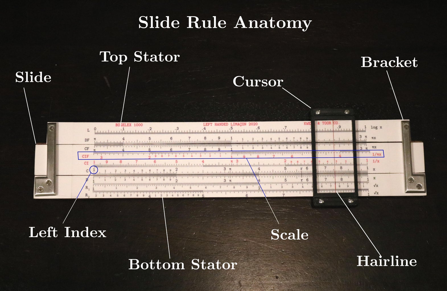
As mentioned before, the slide rule is a calculator. By using various scales, a sliding central piece, and a cursor (the outermost sliding piece with a vertical red line), the user can multiply, divide, find cubes, cube roots, squares, square roots, sines, cosines, tangents, reciprocals, logarithms and exponents! Not bad for a couple of sliding sticks.
In the 1900s, companies like Keuffel & Esser, Post, Pickett, and Dietzgen produced many models of slide rules, some of which you can pick up and play with at flea marks and ebay for as little as $5-10. For context, check out the pic above comparing my own slide rule and one made by the Post company in Japan some time in the mid 20th century.
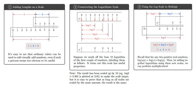
Back in the 1600's, John Napier publicized the concept of logarithms and their weird but useful properties. You might remember from the high school precalc days that the logarithm function can convert products into sums, and vise versa.
Shortly after Napier's publication, people noticed that we could exploit that special property and use two parallel rulers to multiply and divide. Above, you can find a diagram I made in TikZ showing how one might go about generating one of the scales, the "C" and "D" scales.
Step 2: The Generating Function


Eventually, new scales were developed that could perform all the other operations I mentioned earlier, each one using a specific function (based on the base ten log, of course). I've compiled the "generating functions" I used in my slide rule into a table above in case you're curious.
The general strategy for coming up with new scales is:
- Plot numbers at the value returned by the generating function
- Realize that two numbers placed across from each other represent setting their returned values equal to each other
- Sliding the central piece represents adding or subtracting values
- Certain equalities between generating functions reduce to useful operations
Above, I sketched out an example that illustrates the concept. Because the C scale has generating function log(x), and the A scale has generation function 1/2 log(x), we use the facts we know to conclude that these two scales in combination have a useful property: we can use them to find squares and square roots.
The mathematical background for all the other scales is complicated (but interesting), but to save you from my endless blabbering about why slide rule math is so great, I'll restrain myself!
Step 3: Slide Rule Design
The slide rule design has a lot going for it in terms of "good" design:
- Simple & elegant construction of few parts
- Smooth slide and cursor slide action is pleasing to use
- Accurate to around ± 0.2%, enough for applications as involved as some skyscrapers and space expeditions
- If you pay attention, in the iconic Apollo 13 movie you can see slide rules at Mission control AND in the spacecraft itself!
- Teaches user to master concepts of [the infamous] sig figs and orders of magnitude
- Will still work even in the inevitable heat death of the universe since it requires no power
Take time to acquaint yourself and get friendly with all the components of the device, using the anatomy diagram above
Step 4: Tools and Techniques
One of the major goals of this project was to recreate an older technology using modern techniques that would not have been accessible back then. This way, I could push myself to learn a little bit about as many methods as possible that I know I might need later.
Some of the Cool Tools I used were:
- Python
- Fusion 360 (CAD)
- LaTeX
- 3d Printing
- CNC Routing
- Vinyl cutting with Silhouette Cameo
- Metal working, wood working, sewing
I obviously don't have the facilities to afford all of the tools needed for these, but that's easily bypassed when you apply the method of befriending lots of people who can help you out :) The world's filled with resources, whether it's online forums, youtube, friends, teachers, it'd be a shame to not take advantage of that!
Step 5: Materials Breakdown
These are the materials I used, along with sources:
Body
- 1/4" walnut wood (Amazon:
- 1/8" aluminum bar stock (Ebay: https://www.ebay.com/itm/3pcs-1-8-x-3-4-Aluminum-...)
- Screws:
- 2-56 x 5/15" flat head, phillips head (Ebay: https://www.ebay.com/itm/PKG-of-100-2-56-x-5-16-Ma...)
- Printable vinyl sticker sheet (Amazon:
- Matte clear vinyl laminate (Vinyl Expressions:
- Spray lacquer and superglue (Home Depot)
Cursor
- 3d printed PLA
- Screws:
- 2-56 x 1/8" pan headed, slot head (Ebay: https://www.ebay.com/itm/2-56-x-1-8-Slotted-Drive...)
- 0.093" Clear acrylic sheet (Home Depot)
- Red calligraphy ink (Art Store)
Case
- Faux leather, maroon (Amazon:
- All purpose thread, polyester, black (Fabric Store)
Step 6: Design the Scales


The pattern of scales you see above is a design which was made using a python program I wrote. Originally I wanted to try laser engraving the scales and filling the channels with ink, but I couldn't access a laser cutter so instead I went with the vinyl sticker route.
Actual slide rules had their ticks cut with a massive machine called an engine divider, one by one, but in the cursed year of 2020, at the very least we have computers to speed up this process.
Pro tip: The home printer has a surprisingly good amount of accuracy! Use this to your advantage.
Before this project, I hadn't written any major python programs, so this step involved a lot of lurking on stack exchange and the documentation to get some help (but then again, isn't that what CS people do all day anyway?).
The choice and arrangement of scales I settled on was inspired by many historical slide rules
You can find the full program here, although be warned it's not very well written since it was only my first large project so I had almost knowledge of good style and efficiency:
javierlopez6466/Slide-Rule: Slide Rule Programs (github.com)
Even though I literally wrote it, trying to understand some older parts is like decoding ancient texts... clearly my commenting and coding organization skills need work!
Step 7: The Program, Deconstructed

Let me explain the general implementation of the program. The idea is, I need to arrange together multiple scales, each one consisting of hundreds of tick marks which are placed according to a the generating function, which I mentioned earlier. The program essentially generates each scale as follows:
- The main program calls "genscale" which references "pat"
- "pat" places a pattern of ticks based on several parameters. It references "puttick"
- The picture above is an old sketch I made to visualize what each of pat's parameters do
- "puttick" puts a single tick by turning a small block of pixels black
Lots of loops and if else statements let me carefully set up each of the scales to my liking.
At the end, I added on a section to the program that translates the design onto an image which will fit on a 8.5"x11" sheet for printing.
Is this the neatest way to accomplish the task? Absolutely not. Will actual computer scientists laugh at my implementation? Absolutely yes.
But I'm still pretty darn proud I figured out how to make it all work out, despite knowing so little in the beginning.
Step 8: Make a CAD Drawing


I like to sketch out what I'm going to make in CAD (Computer Aided Design) software before I start so I can have a plan to work with.
Fusion 360 is free for students like me (check out their official website), and there are plenty of resources online to learn the basics so I definitely recommend it. I quickly sketched up the design above, using the insert>decal method to apply the jpeg scale images I generated with the program from earlier, allowing me to see what the final product would look like well in advance.
The middle piece has two slotted sides which fit into channels on the upper and lower pieces. L shaped metal pieces screw hold the two outer pieces together, leaving the center to slide free
The cursor is made up of two side pieces which accept screws, and two larger pieces which hold in the "window", which is a piece of clear acrylic with a red hairline inscribed in it to help align readings across scales.
Making a CAD drawing isn't essential in most cases, but it does let me produce the engineering drawings you see above, which were immensely helpful in the building process.
You can find a STEP file here, but be aware that later I had to stretch out some of the dimensions of the cursor parts later on due to 3d printer quirks. This might just be individual to the printer and method of printing unfortunately.
Attachments

Step 9: Cut the Wood Pieces


Walnut is a good sleek looking, durable wood, so I got some pre-planed 1/4" stock. I don't have an electric planer and planing stock by hand is REALLY annoying so this was the easiest way.
The pieces are cut to size according to the diagram above.
Step 10: Route the Channels


The middle piece needs two protruding "tongues" which interface with two channels in the side pieces. It seemed the best way to do this would be with the cheapest possible router from Harbor Freight (because routers do be expensive :| ) and a 1/16" straight bit.
Or rather two 1/16" straight bits because obviously I ended up busting one of them.
I assembled a rickety little jig by clamping some scrap boards onto the table as seen above. Then, the process just involved making many many test cuts and adjusting the horizontal distance and vertical depth of the router until the cuts were adequate.
Making the pieces slide together just right is really difficult because they must:
- Not be so loose they fall apart by themselves
- Not be so tight they can't be moved
Getting the friction fit right literally depends on a tolerance of tenths of a millimeter. Still, after many failed attempts, some of which may or may not have been chucked across the room, I arrived upon a decent little set of pieces.
Step 11: Sand and Finish the Wood


The wood is sanded using 220 grit sandpaper until smooth, then brushed off thoroughly and coated with 5-7 layers of spray lacquer, applied with several minutes in between each coat.
After letting the lacquer dry one full day, a light sand with 440 grit and a final pass with fine steel wool brings the product to a smooth, satin finish.
This finish is easy and not very time intensive, but gives a good result.
Since sand is bad for your lungs, and because lacquer fumes are probably- definitely poisonous, wear a mask when sanding, and do your spraying outdoors or in a ventilated booth.
Step 12: Cut the Metal Brackets


The metal brackets are made from 1/8" aluminum stock. I marked out the shape by scribing lines into the metal using a sharp knife, then proceeded to cut just outside the lines using a hacksaw. Yes, I know it's a "kid's size" hacksaw but it really does work well for precision work.
Change the blade often since they wear down quickly.
After that, the metal is filed down to the exact size required using a file and a cheapo vice. This whole process was kind of time consuming, so I recommend you settle down with a dust mask and a podcast while doing this type of work.
Step 13: Drill Holes


I then scribed the positions of the three holes using an adjustable combination square (I think that's what it's called?) and a sharp knife. I mimicked an awl punch by hammering a random screw lightly into where I needed the hole. That lets the drill bit naturally fall into place. For these screws, to allow a tight pass through fit I used a 5/64" drill bit on the drill press.
To let the angled head of the screws sit flat into the metal pieces, I followed this with a countersink, using a depth stop to make sure all the countersinks were perfect, not too deep, not too shallow.
Life Hack: Don't have a countersink bit? Me neither. Just chuck up that 45 degree angle router bit you never use into the drill press and countersink to your heart's content
Step 14: File the Bevels


I thought the metal would look better and feel smoother with some simple 45 degree bevels on all upper edges.
The sharp corners were taken off once again using the trusty file.
Step 15: Polish the Metal


I don't know much about metal finishing, so I went with a simple low fuss method.
The pieces were sanded progressively with 180, 220, 400, 600, 800, and 1000 grit sandpaper, moving on to the next grit when no scratch marks from the last grit were visible.
At the very end, a rub down with a pad of extremely fine steel wool (Grade #0000) rounds out the job.
The result is a semi reflective smooth finish. Those more skilled with metal may like to apply a mirror finish, though what I arrived at here is more than good enough for my standards.
Step 16: Drill Holes in Wood


Using the newly made parts, the wood pieces and metal pieces can be lined up in place, and the positions for holes marked on the wood. I once again used the trick of hammering in the end of a screw into the wood to get an awl mark / punch for the hole position.
To hold the parts in the right place while marking the hole positions, a little jig is built and a small piece of wood is used to offset the upper piece just the right amount, since the upper stator is shorter than the other parts and is meant to sit in a certain position.
On the drill press, a 5/64" drill bit is once again good to allow for a decent grip of the screw threads.
You can go all the way through, since the metal piece on the other side will cover up the holes
Step 17: Print the Scale Decals


To make the scale stickers, I used the print and cut feature on the Silhouette Cameo, a common home vinyl cutting machine my brother bought once and never used again. After swooping in and collecting the machine, I set to learning how to use it.
It turns out, the method is to generate the scales onto an image which fits onto a sheet of printer paper, which is done in python. 677.33 pixels per inch is plenty good for these purposes. The image also includes blue guide lines. You can find the image above.
After importing the image into Silhouette Studio (the software used with the vinyl cutter), we need to trace out each rectangle the machine needs to cut, using the blue guide lines as reference. The blue lines can be deleted later so they don't print on the sticker sheet. In the picture above, the orange-red lines on the screen indicate where I have told the program I want to cut.
Clearly this process is too complicated to really describe well in one step of an instructables, so I would refer to other online tutorials on how to cut your own stickers with a vinyl cutter.
Important Tip: If you're ever printing a sticker that has a design that goes all the way to the edge, include a "bleed". That means: extend the pattern past the cut line, so you definitely don't end up with annoying unprinted parts on the sticker edges due to imperfect cutting.
Step 18: Cut the Scale Decals


The final design is printed onto a vinyl sheet that has special registration marks – black marks which will let the vinyl cutter know the position of the sheet, so it can cut each sticker perfectly in position.
The sticker sheet is then placed on the cutting mat and cut on the Cameo. For those interested, I found that the following settings were optimal to give a precise cut:
Blade depth: 3, Force: 20, Speed: 2
Brush all the dust off the sheet when it's done cutting.
At this point I might mention that because the scales are longer than a sheet of paper, I had to make the stickers in sections. Unfortunately, this does mean there are seams, but I tried to put them on blank spots where there wasn't any design anyway
The seams aren't that visible, and don't affect the functionality in any way.
Step 19: Apply the Sticker and Laminate


The easiest way to apply the stickers was to dry fit all the parts and screw on all the metal parts with screws too. Then, each scale is placed, making sure they line up exactly right. Parts of the stickers include holes for the screws.
The idea is, once all three stickers are placed for each face, the clear laminate can be applied, which provides a smooth final layer which also adds a lot of useful scratch and water resistance.
Step 20: Flush Trim


To finish off, the pieces are turned around, and a razor blade is used to shear off the excess, leaving a nice flush edge. For the central piece, the weird angle of the tongue meant that cutting from the up side was easier, though still difficult.
As expected I messed up multiple times. If your alignment is wrong by even 0.1mm the scales don't line up correctly. If you place the clear laminate where you don't want it, you can't peel it back, since it will take with it lots of the printed ink. Etc. But in a moment of pure wisdom, my past self thought it was a good idea to print 2 extras full sheets of the stickers, and so I was able to peel off the failures and replace them.
Making extras of components in general is a good idea.
Step 21: Assembly (Minus the Cursor)


Finally, I assembled the pieces with the metal pieces screwed in, noticed more errors in alignment, corrected them, then once I was satisfied I screwed in the screws once again but with a drop of superglue in the holes.
Super glue in screw holes is by no means a permanent hold, and they can be taken out if you really try. But it does offer a decent hold, preventing the pieces from wiggling loose.
Up next is the cursor, an important part we can't forget
Step 22: Cursor Design


The design of the cursor is something I came up with after looking at several preexisting slide rules. The red lines in the plastic (or glass) let you compare readings on two scales. The cursor must slide to any position on the scale. Ideally, the fit is tight enough so that it stays in one position when you need to make a reading, but loose enough that it can moved to any position with ease
As you can see, this project is full of those difficult to make friction fits
Anyways, above you can see the CAD model, whose measurements are based off of a sheet of clear acrylic I found at Home Depot.
The spring is a piece of bent metal inserted into one of the side pieces. When the cursor is attached, the metal should flex slightly, providing a gentle force which holds the cursor in one position where it is needed.
Step 23: 3D Print and Process the Parts

Since my neighbor is a master of 3D printing, he was kind enough to produce prints of the parts I needed from PLA plastic. Some refinement was needed to make the fit and look just right.
3D printing is a whole subject, which you can find plenty of information about right here on Instructables.
Raw 3D prints are a little rough, so I sanded them down and drilled out the holes to size since many came out a little small.
Step 24: Window CNC Routing


Though I was originally going to cut the window piece by hand, my neighbor of the 3d printers also had access to a CNC router at the time, and offered to cut the plastic using that.
After one busted router bit (relatable) and a couple trial runs, the machine was able to cut out the plastic to the perfect size, along with a small ledge which helps the piece fit into the 3d print.
Though these machines are expensive, they amount of precision they can achieve is unbeatable, and I'll definitely be saving up to get them some day, if I have the space for them.
Step 25: Window Hairline


To get the hairline on the window, I found a good method was to scribe a perfectly perpendicular line on the plastic using a razor blade, a ruler, and a steady hand. Then, I filled the cut line with some red calligraphy ink I found lying around, and wiped off the excess on the surface immediately with a paper towel before it dried.
The hairline must be on the surface of the window that touches the scales, otherwise you will get some weird parallax issues. (Meaning, if the hairline is on top, the angle from which you view the cursor will change where the hairline lands on the scales)
A small bit of ink got into scratches I didn't know existed on the surface of the glass, but I quickly realized they can be wiped away with a Q tip dipped in alcohol since this ink is alcohol based.
Know your solvents!
Step 26: Spring!

The spring was no more than a job for a small pair of pliers and some patience making it fit just right.
Originally I used a stiff piece of wire, but I switched to a piece from a large paper clip because the original wire was way too stiff. Paper clip material is not ideal since it doesn't have the resilience properties of spring steel, but it does work, and is really easy to work with.
Step 27: Assembly (this Time WITH the Cursor)


At this point, I could assemble the cursor components, after supergluing the spring piece into the hole on one of the side pieces. Eight teeny tiny screws hold the whole cursor together
Step 28: Make a Case Because Why Not?


Most slide rules back in the day came with leather cases. I had a little too much free time and figured I could make one too, to protect the final slide rule.
It might make sense for me to make another instructable on how to do this, since it is a process. For now I'll briefly summarize.
The material I used was this really nice faux leather which has a maroon dyed leather looking outside and a soft tan backing on the inside, and I used typical black thread.
I came up with the pattern above, which is sewed inside out. A strap placed at 1/1.618 of the length of the case accepts a long flap which closes the case. The upper part of the case has open sides to accommodate the protruding cursor. The corners at the bottom are deliberately curved to account for a weird stretching effect that occurs with this fabric in sharp corners.
The case tends to look floppy when empty because the fabric doesn't really take to ironing flat, but is the perfect size once the slide rule is placed inside it.
Step 29: Final Thoughts


And so, with a final bit of assembly and fine tuning, the slide rule was done. Although the concept isn’t extremely complicated, many of the steps were frustrating and time consuming since I was using techniques I wasn’t familiar with. Still, I know that by pushing myself to learn, I’ve come out of the project having learned so much, ready to apply the skills later to even more ambitious projects.
I hope you might have gained something too, maybe learned about a new technique, a new tool, gained some inspiration, or even just learned a little about vintage math technology you’ll never need to know!
Long live the slide rule,
Javier
Step 30: Bonus: Calculation Example
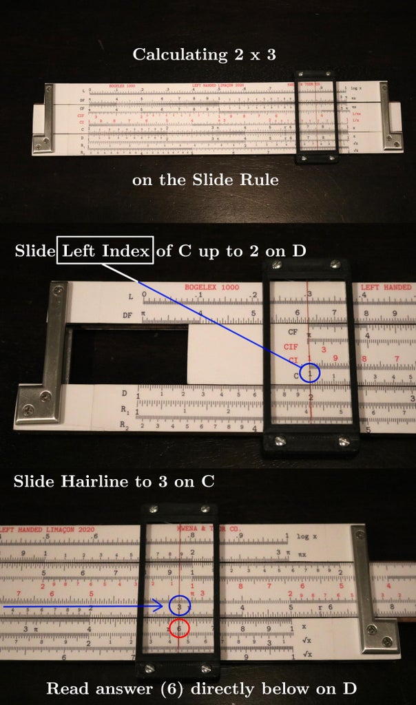
In the future, I will see about making a demo video so the slide action and functionality is more visible. Until then, take a look at the example calculation 2 x 3 = 6 to see that the slide rule is just as functional as expected.

Runner Up in the
1000th Contest


