

Introduction: Smart Mat (Light Your Room)


Hello, let me introduce my third contribution. It is named Smart mat. Would you like your personal room to know when you go inside and when you leave it? Can you imagine a smart personal room to turn on and turn off the your room´s lightbulb by yourself? . It is posiible to reply previous questions with an absolutely, YES.
Step 1: Description
We are going to make a smart mat, It will have pressure sensors, and when you step it, a relay will be activated (Lightbulb ON) if your lightbulb is off or the same relay will be deactivated(lightbulb OFF) if your lightbulb is ON.
In summary, as soon as you go inside your room, it is lighted up and as soon as you leave it, it is blacked out.
So, let's get started :D
Step 2: Materials


I selected a mat with these measurements: 400x500 mm. The mat willl be not stuck with sensors, The base will be making of rubber flooring (see fig1.0), so that, you can exchange the whatever mat (fig.1.1)whenever. Personalized smart mat.
It is needed to get these components: Websites where you will find them: www.digitkey.com,www.ebay.com,www.digitkey.com.
To control circuit:
- (1) Lm324 amplifier(fg 1.2).
- (1) 12V relay(fg1.3).
- (1) 0.1MicroFarad electrolytic capacitor(fg.1.4).
- (1) Lm7805(fg.1.5)
- (1) 2n2222 NPN transistor(fg.1.6)
- (2) 1KiloOhm resistor(fg1.7).
- (1) 10Microfarad electrolytic capacitor(fg.1.8)
- (1) Atmega 328P(fg.1.9) . This microcontroller is included into arduino uno board, but this will be got out from uno board.
- (1) Arduino uno board(fg.2.0). It will only be used to load the programm from PC.
- (1) Diode(fig.2.1)
- (2) 22PicoFarad ceramic capacitor(fg.2.2)
- (1) 10KiloOhm resistor(fg.2.3)
- (1) 1MegaOhm resistor(fg.2.4)
- (1) 5.1V Zener(fg.2.5)
- (1) 16Megaherzios Crystal oscillator(fg.2.6)
- (1) 10KiloOhms trimpot(fg.2.7)
- (2) PCB breadboard universal(fg.2.8)
- (1) 180 Ohms resistor(fig.2.9)
To DC power source:
- (1) Lm7812(fig.3.0).
- (1) 2200uf electrolytic Capacitor 50V (fig.3.1)
- (1) 0.1uf Ceramic capacitor(fig.3.2)
- (1) 1Ampers Bridge rectifier(fig.3.3)
- (1) 200miliAmpers, 120VAC-12VAC Transformer(fig.3.4). The smallest transformer you find, it would be better. Don´t forget we need 12ACV like minimun voltage in its secondary coil.
To Base circuit & mat materials:
- (1) SPST(SinglePoleSingleThrow) Switch (fg3.5)
- (12) Piezoelectric dics. Diameter: 35mm.(fig.3.6) https://www.ebay.com/itm/6pcs-35mm-Piezoelectric-P...
- (1) Cautin with soldering tin(fg.3.7)
- (1) Glue gun with its sillicone bars(fg.3.8)
- (1)Fuse 1A(fig.3.9)
- (1) Enclosure(fg.4.0). I attached the desing to be printed in 3D.
- (1) Electric plug(fg4.1)
- (5M) Rainbow wires(fig.4.2).
- (35x25cm) Rubber flooring(fg.1.0). It will be the base for your carpet, where the sensor will be placed. The rubber flooring ´s measurement has to be slightly less than your caper´s measurement. In my case was 35x25cm. Get it with your specific area here: https://www.homedepot.com/p/Rubber-Cal-Corrugated-...
- (3) SMD rectifier bridge(fg.4.4). https://www.ebay.com/itm/10pcs-DB107S-DF10S-1A-100...
- (1) Breadboard(fg.4.5)
- (1) 2000 Adhesive contact and brush(fg.4.6)
- (1) Carpet(fg.1.1)
- (1) 3.5mm TRRS 4 pole female&Male jack connector(fg.4.8)
- (2) PCB Fuse holder(fig.4.9)
- (3) Terminal block 2 pint(fig.5.0)
Step 3: Base Assembling

Once we got the piezomaterials, we´ll connect four piezo in parallel with each bridge rectifier, see the picture above:

You can see that the biggest area is connected to the other´s biggest area and smallest area connected to the smallest area. So, we are goint to have three parallel connection of four piezo.
Then, we cut circles of rubber, they are going to be stuck on rubber flooring because the piezos'll be stuck on them. It will cause a high sensibility when we step, so that our step will no be compelled.

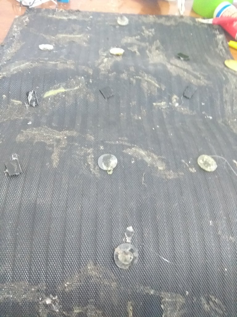
(I had to reuse a mat that I had made before xD, but you will realize how to spread rubber circles out throughout the area's rubber flooring).
Then, we stick the piezos on rubber circles:

(Yes, Once again I Reused materials, piezoelectrics)
Step 4: Base Circuit

Now, we'll make the base circuit that we rectify the signal generated by each footstep.
A part of pcb is needed to place bridges and female connector. So we attach the bridges on pcb.

Then, we join each positive terminal and negative terminal of each bridge. Once We make it, we'll connect the positive terminal to pin 1 of female jack connector & negative terminal to pin 2.

Each paralled connection'll have two terminals (big and small area), so we solder them to in whatever signal pin of bridge, see the picture above:

When we deform a piezo it generates a AC peak signals(negative & positive) like that:
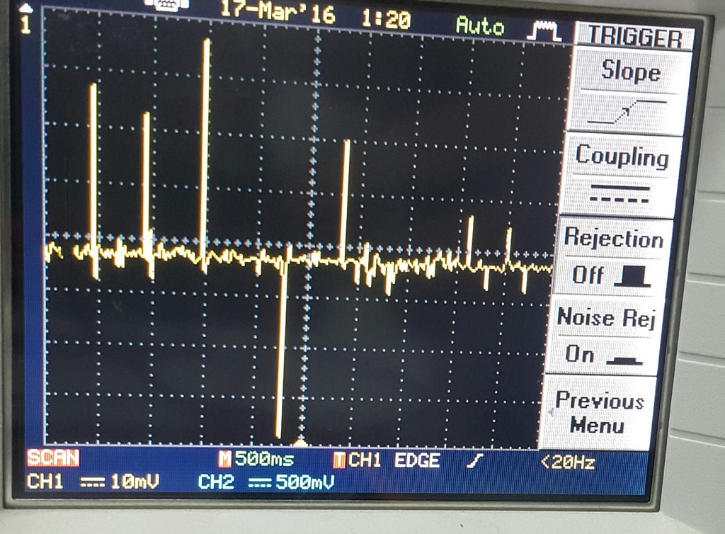
Depending on piezo material &deformation strength, the peak voltage can reach up to 30V. The voltage doesn't matter, what it does, know if there is a voltage, regardless of its value.
So after the bridges rectifier, we get only positive peak signals like that:

At the end, we place the circuit in any corner of rubber base where the female connector points out to outter. Then we'll cover the base with rubber flooring.

Step 5: Power Supply 12V

Now, we will desing the DC power sorce to get 12 volts in direct current. We have the diagram circuit in the following picture:

TRANS means the header terminal block where the primary coil terminals are connected.
TRANS2 means the header terminal block where the primary coil terminals are connected.
AC means the header terminal block where AC current is connected.
The transformer:

its purpose is to reduce the AC voltage, so the kind of signal we'll have in the primary and secondary winding is like the next picture:

The diference is the voltage magnitude: 127Vrms in primary winding && 12Vrms in secondary winding.
The Vrms is the voltage value that pruduces the same heat dissipation in continuos current having a equivalent magnitude. The Vpeak is calculated with the next formula: Vpeak = Vrms/0.707, this will be the value got in your multimeter.
Then we place in the secondary winding a bridge rectifer, we get only positive sine wave like that:

We notice frequency of wave is doubled. To purify the wave, it is needed to place in parallel a capacitor and then the lm7812 to get DC 12Volts.

Remember, always test the circuit in a breadboard before soldering on pcb.

(As you see, I recycled some capacitors of diferent value, connectig them in parallel(to increase the capacitance) and the bridge rectifier was built with four diodes recycled hehehe).
Step 6: Control Circuit Part1: OAMP

This is a fundamental step to interprete the voltage generated by piezo into a footstep.
We´ll need an Operational amplifier:
https://www.instructables.com/id/Personalize-an-In...

An amplifier is a complex ensemble of transistors to do logic & mathematics operations, signal amplification, filters and so on. Lm324 is an integrated circuit that has 4 amplifiers in its inner. Just one amplifier will be needed like a comparator.

To understand the control circuit part 1, we connect in parallel a 1megaOhm resistor(R4) & 0.1microFarad capacitor(C3) because we need to filter the voltage generated a little bit and de high resistor allow us not to loose energy. The negative bridge terminal is connected to ground in all the circuit. Rectifier means the male audio connector that will be joint to female audio connector to recieve the signals of piezos.

We can see the OAMP(U2:A) has a negative, a positive input(pin 2&3) and an output(pin 1). OAMP is powered by 12V with its ground. The main purpose of this circuit is to compare a small reference voltage in the negative input with the voltage generated between postive input and ground by piezos. Placing the trimpot(R3) as variable resistor, it is connected in series with R2(180Ohms) to determinate the reference voltage in negative input. You need to measure the voltage in positive input without stepping. The reference voltage must be higher than voltage of pin 3 (without stepping). When we step the mat, the voltage of pin 3 has to be higher than reference voltage, when it happens, the output gives an voltage that is regulated to 5.1V by Zener 5.1V and 1kOhm resistor in parallel(R1). The atmega328P can only read directly until 5 volts in each analog pins, Zener 5.1 will prevent damage it.
In summary, we convert the analog signal of piezo in digital number. there are only two posible options(0,1) in the output: 1 equals 5V when we step the mat(voltage positive input higher than reference voltage), 0 equal to 0V when nobody steps the mat(voltage positive input lowest than reference voltage).
Step 7: Arduino Program
The arduino programm is attached with its explanation.
Pin A0 is used to read the output value of OAMP. Digital pin 6 is used to active relay (turn the lighbulb on)
Attachments

Step 8: Control Circuit Part 2: Atmega 328P & Output Circuit


Ok, now we need tu pull the atmega328P out from arduino. See the picture above, that is the equivalent circuit of arduino board.

It works with 5V, we get it from lm7805 like that:

Where V1 is the 12Volts output from lm7812 and C4 is the 10microFaradad between 5V and ground.
Remind, the digital pin 6 in arduino actives relay. Now you can see in atmega329 is pin 12(D6), here it is connected the next circuit:

The Q1 transistor increases the current of relay's coil, the coil generates a magnetic field that actives the inner relay's swtich. The D1 diode takes the energy stored in the relay's coil when you switch the current off. Without the diode, the energy has no place to go and will cause a large and probably destructive voltage spike.
The relay's connection is like that: common pin is connected to whatever AC terminal. Normally open pin is connected to any lightbulb terminal. Normally closed pin is connected to nothing. The fuse is to avoid short circuits. When D6 is HIGH, the switch's position shifts, now the common pin is connected to normally open pin, so that, the lightbulb is switched on.
The switch is placed in parallel, that switch is your room´s switch. So we'll be able to switch on by hand or automatically stepping the mat. But if you switch on by stepping, you'll not switch it off by hand with this connection.If you don´t care then pass to next step. I made this project with this connection. But if you want to turn on and off by hand or automatically, regardless the switch's position as staircase wiring. Below I explain how to do it. The next circuit I tested on breadboard and it worked. However you will need to buy more components and write a different program that works. This instructuble was no designed with the next circuit, but you can adapt it.
Staircase electronic circuit
Look at the next diagram to make a staircase wiring using relay and a three way switch.

We need to understand that regardless of switch's positions and relay's state (activated or deactivated) the lightbulb can be switched off or on. For instance: if switch's positions is off and relay's state is on, it will have to light up. If switch´s position is on and relay's is off, it will have to light up. see the next binary table:
0 is LOW state and 1 is HIGH state.
| Switch's state | Relay's state | Lightbulb´s state |
| 0 | 0 | 0 |
| 0 | 1 | 1 |
| 1 | 0 | 1 |
| 1 | 1 | 0 |
To do this possible, we need to know if the lightbub´s state, if we know that, the next change of relay´s state or switch's state will determinate the change of lightbulb's state. Knowing lightbulb's state is the purpose to the next circuit. The program you'll write in atmega328P, will have the purpose to change the lightbulb's state. How will you be able to change the lightbulb's state regardless of switch's and relay's state if you don´t know the lightbulb's state?

Let´s explain it. We need to know if there is a current flowing through the lighbulb. If there is, the atmega must know it. So we connect a bridge rectifier BR1 to rectifier the AC wave. The AC wave has 127VAC depending of your location. It´s a high voltage, so we need to filter it & reduce it. That is what it makes this part of the circuit:

Where C1 filters the signal and the resistors(R2 & R3) in series connection produce a divider voltage. Each resistor depending of its Ohm value, has part of BR1 voltage (126VAC beacuse of losses energy by bridge). But, ideally we take 127VAC. R3 voltage is the value that we need to get, 6 volts. Acordding to the next formula of voltage divider:

To determinate de resisor(R3) that has 6V, we isolate R3.


So, R3 value was demonstrated. Now, we analyse the second part:

It is recommended to isolate the high voltage power and low voltage control circuit for circuit protection. To do this we need an optocoupler U1 that actives a innner transistor by inner led's light. Q2 is activated when AC current flows through lightbulb, the bridge rectifier with C1 & resistors transforms into wave rectified. The voltage of R3 actives the Q2 base, so that a current flows through U1's led. The U1's led in HIGH state activates the base of inner transistor without a contact connection because of light features. The electromagnetic wave(light) travels through a vacuum. So, the voltage of transistor´s colector will be measured by Atmega. When the transistor is activated, it means there is not current flowing through lightbulb, when the transistor is deactivated, it means there is current flowing through lightbulb. We have a inverse logic circuit here, see the next table:
| Lightbulb's state | Voltage of transistor's colector | Atmega's interpretation |
| HIGH | 0volts | The lightbulb is On |
| LOW | 5volts | The lightbulb is Off |
Understanding this, you will be able to adapt the arduino program to this purpose.
Step 9: Assembling Electronics


Once you tested it the circuit and it works, it´s time to place it to pcb. The pdf electronic diagram is attached above. The proteus file is attached if you want to place on virgin pcb. I didn´t make it like that.

There are three headerblocks, one is to connect the transformer, other to connect the lightbulb and the last to connect the room´s switch. Look at the complete electronic diagram to see their connections.
Soldering all the components, the male jack connector is soldered with the rainbow wires, see the next pictures:

Depending how many distance there is between mat and box control, you'll determinate how many meter of rainbow wire you'll need. A wire is soldered to ground and the other wire to OAMP's positive input.

I attached the pivol box file in .dwg, so that it can be printed by 3D printer. It is the box where we'll place the circuit. See the next pictures:


The front of box, the electric plug will be attached by sillicone. As you see, I recycled one from a charger that
didn´t already use to work. A plug terminal is soldered with switch and the other switch's terminal is place in its respective headerblock's terminal(look at the complete diagram above).


Step 10: Implementation
I hired an electric service to implement the smart mat. At first I test the system to confirm if it worked, it did:
The electrician gave me the AC and room's lightbulb terminals, I needed 12 metres of awg 12 cable. Let me repeat it again, you need to test if it works like the previous video: get a socket and make the right connections. The electrician also place an electric outlet close to the mechanical switch.
Let you imagination fly, see you later ;)


