

Introduction: Smart Talking Fluid(sanitizer) Dispenser Using Arduino MEGA


- Here is my entry for the ARDUINO contest. Arduino is a microcontroller board, using which you can literally make anything you can think of! Unless you're too tired to get your hands dirty. LOL
In these struggling times, which gave our world a lifelong lesson to maintain hygienity by either washing or regularly sanitizing the hands to avoid the spread of the CORONA virus. I still miss the time when corona was just a beer.
So to motivate the visitors in your home/office or ideally any place, I'll show you how I built this smart speaking dispensing machine that can dispense any type of thin fluids(Sanitizer in my case).
This machine is made using an ARDUINO MEGA microcontroller board for some reasons which will be discussed ahead.
I would recommend you to at least give one try to build this machine , trust me you'll be very satisfied with the end results
Supplies
- Arduino MEGA - obviously
- An enclosure of your choice to fit everything into (I used a rectangular plastic box )
- A tank of any type that can fit into the enclosure(I am using old mineral water bottle)
- HC-SR-04 ultrasonic sensor
- GLCD(Graphic LCD) ks0108 128x64 monochrome (green backlight)
- Diaphragm pump(5 volts) This is where I struggled a lot, find a pump that can run on 5 volts, and does not require primping, and is diaphragm-based.
- The flexible pipe that fits the mouth of the pump.
- A nozzle that fits to the pipe chosen.
- Micro USB type B female jack (or any type of connector accessible to you)
- 5-volt wall adapter
- Boost converter
- A lot of jumper wires, ribbon cables
- SD card module with a 4GB SD card.
- Any small speaker with a built-in amplifier(I made my own using old leftover parts). A typical AUX speaker will do good.
OPTIONAL STUFF:
- RGB led lights
- 4 channel relay module
- Diffuser sheet (Extremely optional)
- Black vinyl sheet to be sticked on the top of box to make it look elegant.(EXTREMELY optional depending on the type of container being used)
- Foam sheet to create the desired cutout for light to come out.
- 12 volt DC jack(female)
TOOLS :
- Soldering IRON or a Soldering station(Whichever you have)
- Hot glue gun.
- Screws/nut bolt with matching screwdriver.
- Hobby cutter/ knife .
Step 1: Making Cutouts on Front Panel of the Box and Placing the Foam Sheet and Diffuser Sheet on the Back Side


I'll start off by placing the GLCD on the top of the front panel.
I usually cut plastic by heating an old knife and sliding it slowly on the markings I made.
After GLCD, I'll make the cutout for the ultrasonic sensor.
OPTIONAL THING :
If you're using a box-like me and have a vinyl sheet or any type of sticker sheet(Black colored) so you can also use a foam sheet/cardboard sheet along with a diffuser sheet to make it look even more elegant.
I first cut the foam sheet to the size so that it can fit inside the lid of the box(The front panel of the end machine)
Then I made the cutout matching the pattern on the lid.
I also cut the diffuser sheet with the same size as the foam sheet and stuck them together.
Step 2: (OPTIONAL STEP)Sticking the Vinyl Sheet and Cutting It Along the Box Cutouts and Placing/fixing the Components


After cutting the foam sheet and diffuser sheet, I stuck the black printed vinyl sheet on the box lid and let it sit for an hour or so.
After which I made the cuts along with the box pattern(bevel shaped) which makes it look like the pattern is intentionally made for light to come out which looks pretty cool!
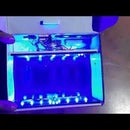
Step 3: (OPTIONAL STEP)Fixing RGB Led Lights Along With the Relay Module


I carefully stuck the LED strip so that it lied just below the cutout made on the lid. So that when the light glows it is throwing most of the light on the diffuser sheet and it glows bright.
This is really an optional step only if you want a soft led touch around the machine.
I used a bit of flex glue so that the LED strip is really rocked tight to the box.
Now I had the 4 channel relay module and the LED strip requires only 3 channels so I used the 4th channel for controlling the pump. The pump won't be supplied by the 12 volt supply but rather would be supplied directly by the 5 volt USB jack via the relay so that if LEDs are not wanted to be ON the pump would still work.
And moreover, the pump I used worked well at 5 volts.
Step 4: Fixing the Fluid Tank(OLD Bottle)


I measured the radius of the bottleneck and marked a circle of the same size on the top end of the box.
But to fix the bottle firmly I had to enlarge the circle a bit so that the bottleneck fits tightly in the box .
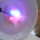
Step 5: Fixing the Fluid System


The next step is to fix the diaphragm pump along with the pipe and the nozzle.
I placed the nozzle at the bottom center of the box and marked the necessary cutouts and after cutting them, I glued the nozzle with a lot of hot glue so that there is no leakage in there.
The pump output connects to the nozzle and the pump input goes inside the bottle from a tiny hole which I made using a sharp pin and then expanded it using scissors.
I used a PVC pipe holder to fix the pump onto the box using a nut and bolt. The bolt was a bit long which proved to be beneficial as now it can act as a holder to hang the entire machine on some wall or a plain surface.
Step 6: Fixing Power Jacks on Any Desirable Side


This step is not that mandatory.
If you don't want to cut the wires of the wall adapter and keep it fixed inside the machine, having the DC jacks is a good thing you can do.
I used a micro USB B-type female connector. I also added a 12 volt DC jack separately for the LED strip so that I can decide when to turn the LEDs ON or OFF.
Or what you can do is have one more boost converter and step the 5volts to 12 volts and drive the LED strip . Or you can even use a 5 Volt led strip but I had only 12 volts one left with me so I added a DC jack.
I connected the 12 volt DC jack output directly to the LED strip via the relays on the relay module.
Step 7: Fixing the Speaker

You can directly fix the AUX speaker inside the box. But I personally recommend to rip it apart and remove the battery and directly connect the power supply of the amplifier to the 5 volts from the DC jack so that you don't have to charge the battery every few hours.
You'll also have to cut the AUX wire and get the signal and ground wires and keep them ready to be connected to the Arduino.
So basically you have 4 wires in total, 2 wires for power(5 volts) and 2 wires for signal .
Step 8: Fixing the Arduino


Having Arduino mega fixed on the box along with the USB female jack accessible at the outside so that we can upload/modify the code if required in the future. You need to be careful here as you have to connect literally everything to the Arduino mega so have enough room for working around it .
Step 9: CIRCUIT SCHEMATIC


You can refer to the above image to make the connections, but there are few changes in actual implementation as the schematic I drew was about a month ago, now this project has got a lot of changes, but you need not worry as I will specify each and every connection to be made.
Start off with GLCD connections to the Arduino mega.
The image is attached above.
Next thing is to connect the SD card module to the Arduino mega. The image is again attached.
The relay module used here is -ve logic one so get a similar one or you'll have to modify the code a bit.
So the relay module +5volt and ground will be connected to the 5volt DC jack as Arduino won't be able to supply enough current.
The 4 signal pins of the relay module named IN1,2,3,4 will be connected to Arduino analog pins A0, A1, A2, A3
3 of the channels would be used by led's and 4th channel for Pump control
You can use any pins but I tested and tried these pins and they work well.
Ultrasonic sensor :
ECHO: D39
Trigger: D38
SPEAKER amplifier:
Signal input of amplifier goes to D5 of Arduino mega(I do not recommend changing this pin not even in the code)
It has got something to do with the timers inside the microcontroller which are connected to few special pins only. Also, the PCM library used recommends using pin no D5 on the mega board.
These were all the connections to be made to the Arduino mega.
POWER CONNECTIONS:
I'll be using the boost converter to supply the Arduino mega via the 5 volt USB jack rather than directly powering it. This is because when I tried powering it using the 5-volt adapter directly via the Vin pin it was resetting sometimes which showed a lack of enough voltage to keep the peripherals ON and keeping the uC ON at the same time. so I Boosted the voltage at around 6.3 volts and then fed it to the Vin pin of Arduino mega and everything worked fine then.
The boost converter also features few capacitors which provide a smooth supply to the uC board ie the Arduino mega board.
Step 10: Connecting Everything Together


Now I used custom-built ribbon cables which have male and female headers soldered at the ends. Because jumper wires are too short at times and too costly when you have to connect a lot of connections.
If you don't want to solder a lot go with jumper wires simply and if you actually wanna get into soldering and all make wires as I did but be careful as one single error in connection and it's not gonna work.
Step 11: COPY the Audio Files to SD Card.
This is the most important step you'll have to do before turning the machine ON .
- Insert the SD card in your PC using an SD card adapter
- Format the SD card
- Paste the files attached herein into the SD card
- Remove the SD card from the card reader and put it inside the SD card module which is there in the machine.
NOTE: Do not rename the files or else it won't play while machine is working.

Step 12: Dumping the CODE on the Arduino Mega
This is the .ino file that you need to dump on the Arduino board, but before that, you need to install few libraries
openGLCD.h
SD.h
TMRpcm.h
You can either use the library manager of the Arduino IDE or can manually download the .zip files and install the libraries using add .zip library.
Attachments
Step 13: OPTIONAL If You Want to Change the Graphics Displayed on GLCD
Do it only if you know C++ and C well.
You need to create an image of 128x64 pixels, which I did use photoshop.
You'll have to save this image as a monochrome bitmap and generate a hex code of this image.
Now you'll have to paste this entire code into the already present matrixes which look like:
GLCDBMAPDECL(Welcome)={
128,
64,
0xFF,0xFF,0xFF,0xFF,0x1F,0x0F........................
You just need to change the hex code only and nothing else.
I found an instructable by "theorycircuit" which explains how to do the above steps
The link to that instructable :
https://www.instructables.com/Interface-GLCD-with-...
If you are okay with the graphics as shown in the video simply skip this step, no need to unnecessarily scratch your head .
Step 14: TEST It!
Connect the Arduino to pc via a USB cable.
Dump the code
Remove the USB cable
Connect the USB power jack and 12 volts DC jack as well and power it all ON.
If everything goes well it should work as shown in the video.
I hope you enjoyed this instructable.
Happy learning.............

Participated in the
Arduino Contest


