

Introduction: Smart Wooden Dummy


Problem statement
Hi! This instructable will walk you through the step to create a Smart Wooden Dummy, which is an electronics Marts training aid for developing a data and statistics driven training regime. While many sports have standard metrics to base training off of, those measurable stands are sometimes hard to find in martial arts; this project aims to remedy that, by presenting in-depth instructions that someone who is not an electronics master can follow, along with additional in-depth information for those who wish to get to the details.
Smart Wooden Dummy Description
This device will sense strikes as you use it, and measure total number of strikes, hit/miss ratio, reaction time, and peak and average force used. You can adjust the round time, required strike speed, required strike force, and calibrate it to your specific setup. This project uses the already-built wooden dummy described in this instructable: https://www.instructables.com/id/Karate-Wooden-Dummy/), and can be adapted for use on other style wooden dummies. Total cost is around $480, assuming you cannot salvage parts.
This is accomplished using sensors to create six target areas; Accelerometers with LEDs/Buzzers in the three arms, and LED’s/Buzzers combined with large custom limit switches for Hi/Mid/Low “trunk” targets.
All of these are wired back to a main box, which includes an LCD screen to display statistics and user interface, dials to adjust round parameters, and start button.
Inside this enclosure, all the processing is accomplished using three Arduino Megas (due to number of inputs and processing speed), connected in a Master/Slave configuration. One slave handles the arms, one slave handles the trunk, and the master handles the coordination between the two, and the user interface panel. (see block diagram and schematic). Much more detail is given in the following steps.
A lot of time and effort has gone into this project; I hope you enjoy, and get some use out of this instructable! If you have any ideas/comments, or if you make your own, please let me know!
Step 1: Parts List and Tools

Parts
NOTE: The attached spreadsheet includes links to the product page for all parts listed below
# Item (Vendor) Price (# used) Total
1 Arduino Mega (Amazon) $14.99 (3) $44.97
2 ADXL377 - High-G Triple-Axis Accelerometer (Adafruit) $24.95 (4) $99.80
3 Jumbo red LED (Digikey) $0.50 (6) $3.00
4 LCD Display (2pk) (Amazon) $4.95 (1) $4.95
5 8 Con. cable, 100ft (Amazon) $40.00 (1) $40.00
6 PVC, 1"x10' SCH 40 (Lowes) $4.17 (1) $4.17
7 1" PVC Cap (Lowes) $0.89 (3) $2.67
8 Large project box (Amazon) $32.99 (1) $32.99
9 Variable resistor dials (Amazon) $12.86 (1) $12.86
10 Buzzer (pack of 6) (Amazon) $5.99 (2) $11.98
11 Variable resistors (Amazon) $16.99 (1) $16.99
12 PVC 1" coupling (Lowes) $0.60 (3) $1.80
13 Arduino power splitter (Adafruit) $5.00 (1) $5.00
14 Screw terminal blocks (Amazon) $32.00 (3) $96.00
15 Cable gland (20pk) (Amazon) $12.00 (1) $12.00
16 Power Switch (pk 5) (Amazon) $8.50 (1) $8.50
17 Bush button (pk 5) (Amazon) $10.99 (1) $10.99
18 Power Cable (Adafruit) $8.00 (1) $8.00
19 Arduino Case (Amazon) $10.00 (3) $30.00
20 Plastic cable straps (12) (Lowes) $1.04 (1) $1.04
21 Door hinges (Lowes) $3.08 (5) $15.40
22 Bolts: 6/32x3/8 (pk 14) (Lowes) $1.28 (1) $1.28
Consumables
1 Heat shrink (100ft) (Amazon) $7.50 (1) $7.50
2 PVC Cement (Lowes) $5.80 (1) $5.80
3 Liquid nails, 10oz glue (Lowes) $1.80 (1) $1.80
4 solder (0.35oz, 0.031") (Amazon) $3.50 (1) $3.50
TOTALS: $482.99
Tools
i. Wire Strippers
ii. Soldering Iron w/solder
iii. Drill
iv. Dremel, hot knife, or saw (for LCD hole in box)
v. PVC cutters or saw
vi. Helping hand (alligator clip wire holder)
vii. Small adjustable wrench
viii. Small Phillips screwdriver
ix. Needle nose pliars
x. Computer with Arduino program and cable
Skills
As much as I tried to avoid it for beginner’s sake, this project does have spots that require soldering. If you do not have much practice at soldering, see this link for excellent directions to pick up this relatively easy skill. https://www.instructables.com/lesson/Soldering-1/
Safety
Project-wise, standard safety protocol applies; only solder in a well-ventilated area, and wear proper protective equipment when using tools (safety glasses, gloves, etc.). From a martial arts perspective, this instructable has the following disclaimer: this project should not be used except under the guidance of a competent martial arts instructs. The reader builds and uses this training aid at his own risk, and is responsible for ensuring the quality/safety of the machine before each use.
Attachments

Step 2: Making the Arm Sensors


General steps:
I used extra-heavy duty PVC for the arms; they have been working well, with no signs of wear.
For the Arms:
1. Cut three sections of 1” Schedule 80 PVC, XX inches each
2. PVC glue a 1” union to each piece.
For the sensor heads:
1. Cut three 2.5 inch sections of the 1” Schedule 80 PVC
2. Drill a XX” hole though the center of the 1” PVC cap for the jumbo LED. Go slow here; if you get it just right, the LED will be so snug when pushed in it won’t need any glue (use a flat head screwdriver between the leads to push it in).
3. Once the sensors are installed, glue the cap to the 2.5” pipe. I prefer not to glue the sensor head to the arms, just in case I ever need to work on them.
For the sensors:
1. Here is the tricky part; these need to be soldered for reliability. I bent the ends of the wires into little hooks for the Buzzer/LEDs so they would be mechanically strong. For the Accelerometers, the Helping Hand is a must; trim any excess sticking through the other side with side cutters as needed. I used a 12-ft section of cable per arm. The color code I used for the 8-conductor cable to each arm is as follows:
a.Red - Buzzer/LED Voltage
b.Black – Buzzer/LED ground
c.White – Accelerometer 5V power
d.Green – Accelerometer ground
e.Yellow – Accelerometer X axis signal
f.Orange – Accelerometer Y axis signal
g.Brown – Accelerometer Z axis signal
h.Blue - Accelerometer Test (Not used; see below)
Assembly
1. NOTE:Before assembly of the arms, you will want to hook them up to an Arduino and run the test program to make sure everything is reading. Details and program under the “testing” step.
2. Once the sensor and LED/buzzer combos are soldered together, and the LED pushed into the hole in the cap, slide the 2.5” PVC over the cable and seat it in the cap. If you are confident, you can fill the cap with silicon/construction glue for durability and ruggedness. Personally, I stuffed foam in the caps until everything was tight, then put a piece of tape of the top to keep it all in. That way if I want/need to make modifications, it’s not entombed.
In-depth:
These sensors provide an analog output, from 0-3.3V. They measure from -200g to +200g, so 0g would put out 1.65V. They also measure in all three axis (x, y, z).
For the LED/Buzzer, I wish I had put them on their own wires, instead of having them in series with the blue wire going to the test pin of the accelerometer (which was not used). If you want to do that, you will have to slightly alter the programs to set 2 digital outputs high instead of just one to accommodate.
Step 3: Making the Trunk Sensors


For the Limit Switches
1. My wooden dummy already had the strike pads (from TigerClaw.com), so I was just able to use those. However, if your wooden dummy does not have pads, you will need to make/buy some. Of course, the original wooden dummy had no padding, just wood, so you could use a board if you were inclined.
2. Attach door hinges (2 for the large pads, 1 for the small) using #10-24x1” bolts. If you want, some red locktight would not be a bad idea.
3. For the wire terminals, I wrapped the wire around a 1-1/2 sound-head screw (from a drywall anchor kit) sandwiched between two fender washers. I had to use a drill bit to enlarge the holes in the fender washers slightly.
4. A couple inches below where the top of the pad will be, insert the terminals to the backboard about 3” apart. At a corresponding height, on the back of the strike pad screw a 6-in Steel Brace (Lowes Item # 64735).
5.Finally, take two 3” screws and add washers (to protect the pad), push them through the pad holes, and add the springs to the back. Screw them into the board until the board has just 1/2” of travel before the brace makes connection with the terminals. The board should move freely over the screw (on 3” screws, the top near the head does not have threads).
6. Note: I chose to have the three cable from the limit switches get spliced into one 8-conductor cable to go the box, and same for the three cables coming from the indicator PCV heads. This is entirely optional, and not needed. I uses a little less cable, but is more work if you choose to do it.
For the Accelerometer
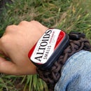
1. I choose to mount the back accelerometer in a small Altoids tin (for easy access if needed).
2. Drill a hole in the bottom of the tin, and line the tin with Moleskin.
3. Push the cable (10ft) through the hole, and solder the accelerometer using the same color convention as the arms. Use a cable tie anchor inside the tin for stress relief.
4. Stuff foam in the container to keep everything locked in place, close the tin, and seal shut with electrical tape.
5. Mount to back of wooden dummy with a small piece of strapping and two 1” screws.
For the LED/Buzzer combos
1. A LED and buzzer will be soldered together in the same way as the arms for each of the three “indicators”; however, there will not be an accelerometer in each like the arms. This is because the entire trunk feel the vibrations on any target struck, so it would be hard to distinguish which was struck; therefor the data from one sensor is paired a limit switch to determine which target was struck and the force. For this application, you can use ¾” PVC and cap instead of the 1” for a smaller footprint if you wish.
2. Drill a hole completely through the wood the exact diameter of the PVC PIPE (not cap) that you are using. Cut a section of pipe that is just long enough to go through the board with a fitting on each end. I used hot glue to secure the cable in the pipe stub for strain relief. For the back fitting, I had some 90 degree elbows on hand, so I used those; a cap with a hole drilled in it may make for a more finished look though.
3. This solution is kind of unique to this type of wooden dummy (with the flat board); if you have a round style, you can drill a shallow hole for the PVC head (minus the back fitting), and a narrow hole all the way through for the cable. Then seal it in with wood glue/construction glue.
Step 4: Making the Enclosure


I had a box not being used that worked for this project, so the one I specified in the parts list will be different. While the cable glands are not technically required, I would definitely recommend them so that is a cord gets pulled, it does not pull on the Arduino connections.
First, measure exactly where you want the display and screen to be located on the front. I have included the PDF in the first step the template for the dial labels. Just print them to a full-page shipping label. Once I did that, I sandwiched the label between two thin boards and clamped them; then I drilled the holes for the dials through everything at once. This made for clean, round holes, vs. trying to use an exacto knife. A note; the dials have a tiny tab t the side to keep them from spinning around. You can cut those off and just make sure they are very tight, or you can do like I did and drill a tiny hole beside each main hole for it to go in.
For the hole for the screen, I actually used a grinder to make straight cuts (and overshot a bit, as you can see in the finished photo).
Now, my box had a metal backplate (removable plate to mount components). I did not want to mount arduinos directly to metal, and risk shorting out a connection, so I got the clear plastic Arduino cases listed in the parts section. However, with the plastic enclosure I listed, that would not be a problem and you can do without them. The arduinos are just bolted down with little 6-32x3/8” bolts. Notice I left room between them for the cable tie anchors.
A note on the LCD screen I got; there was a lot of extra “wire” poking through the back, which interfered with mounting; I just cut off the extra with side cutters. Also, the LCD needs the two pins to the left connected for the backlight to work. If yours comes with a jumper, great. Mine did not, so I just soldered a tiny piece or wire across them.
Another note: I included a dial for calibration; that was thinking toward future improvements. I plan to make the calibration routine a subroutine in the main program, where you use the dial to adjust the reading to the actual, and then the program stores it in the non-volatile memory of the Arduino. You will get to the calibration by long-pressing the start button.
Attachments
Step 5: Wiring and Connections


General steps:
I made the investment in terminal blocks to go on top of the arduinos; to me, completely worth it. They provide the security of a soldered connection, with the flexibility of a breadboard. If you are confident I your soldering, you can buy arduinos without the headers installed, and just solder straight to the board.
For all the connections to the terminal blocks, it is important that the wires are either tinned (a small amount of solder added to the end to make the ridged and less fragile) or use ferrules. Considering I was pulling them through small cable glands, I chose tinning because it is smaller.
For the connections inside the box, I used two short sections of 8-conductor cable. Notice how I placed the cable tie anchors; you want the lid to open all the way without straining the cable, but you also want the lid to close without crimping the cable in half.
While pictured above, the main PDF also includes the wiring pinout diagram. This where cable tie anchors are a huge help; my box already looks like a rats nest, but I can trace where each wire goes. Without anchors, it is almost guaranteed to get something wrong. Important: when placing anchors, keep in mind that you want to be able to get to the power ports and programming ports later.
The three-headed power adaptor from Adafruit will plug into each board, and the extra just get tucked away. While I have a power switch on the cover, I ended up deciding the bought switch for testing was easier, and used it in the final product.
Pretty much every cable plugging into the arduinos will be coming from outside the box or from the lid; exceptions are the bus cables. The I2C bus and common ground will need their own jumpers made. Also, there is a wire going from the 3.3V pin to the AREF pin on each slave, which will both need a jumper made.
In-depth:
The analog pins of an Arduino return an integer form 0 to 1023 based off a reference. The default reference is 5V. So 0V would return 1, and 5V would return 1023. However, the accelerometers are outputting 0 to 3.3 volts. While the default would work, you lose some resolution by not using the full scale. By tying the pins together and adding a command in the program to user the Analog reference pin, 0-123 equals 0-3.3 volts, giving much better resolution. Example: based off of 5V and a -200 to +200g sensor, a reading of 500 vs 501 would be a difference of 4.888mV, or 0.592g. Using 3.3 volts as reference, a change from 500 to 501 is 3.23mV, or 0.39g; much better.
Attachments

Step 6: Programming
General steps:
Below you will find the Arduino programs (sketches) for each board, as well as the testing and calibrations programs. The should be fairly plug and play, with one exception; there are two different libraries that can be used to control a I2C LCD screen. Both are good, but they are not interchangeable. It is important that you download the one I used before you try to load the programs. Follow this excellent link for step-by-step directions to getting it on your computer:
If you are new to Arduinos, you will need to download the Arduino software (IDE), found here: https://www.arduino.cc/en/Main/Software . Once you open the sketches below in the software, follow these directions to load the sketch to the device: https://www.dummies.com/computers/arduino/how-to-upload-a-sketch-to-an-arduino/
One think I found, is that switching between multiple Arduinos, there will be given different ports. So you may need to select the correct port again when you switch which Arduino is connected. Also, for testing, the programs will send messages back to the computer using “serial” commands. To view these, select “serial monitor” under Tools in the program, and select 9600 as the baud rate.
In depth:
This project uses I2C protocol (sometimes called TWI) to talk between the arduinos and the LCD screen. It allows a master to connect with up to 255 “slave” devices. It is a good, simple, fast protocol that only uses 2 wires. However, it is not a long distance protocol, going only about a meter. This means that it is for internal to the box only; you cannot locate the screen 10 feet away and expect it to work.
An important note: many LCD screens will have 0x27 as the I2C address, however this is not always the case. If you screen does not work, use this excellent walkthrough to discover the address for your LCD: https://forum.arduino.cc/index.php?topic=128635.0
Here is a VERY simplified look at the program (sketch) and how it is set up:
Master
1. Create variables and set up libraries (setup, when first turned on)
2. Read dials and scale their inputs; display to screen and wait for start button to be pushed.
3. Start button pushed! Start round timer.
4. Create a random number between 1 and 6 (sensor number; 1-3 for arms, 4-6 for trunk) and send it to the slave:
a. SLAVE: Sit here and wait for number.
b. Number received! Start monitoring sensors to exceed threshold.
c. Sensor has exceeded threshold! Continue monitoring to get the peak force.
d. Is the sensor that was struck match the number the master sent (was the right target hit)? If it was, send back peak force. If not, send back “1”
5. If reply is not one, record values. If it is one, add 1 to the “missed” counter.
6. Is round timer expired? If not, go back to “random number” step and start again.
7. Round finished! Calculate statistics (hit ration, average hit force, etc.)
8. Display statistics to the LCD screen. After timeout, return back to “read dials” step.
Step 7: Calibration


This device will record the force the sensors feel, which is fine for your personal training. Just compare your personal number on the same machine to see if you are improving. However, if more than one person has one of these, and you want to compare your numbers in a meaningful way, you will want to use impulse instead of g. Since the rigidity, weight, and materials of each wooden dummy will affect the force felt by the sensors, you will need to calibrate your machine for your setup. Below shows to do a two-point calibration of your system.
To create an impulse to calibrate with, you need a known weight traveling at a known speed. I accomplished this using a 2lb (for the arms) and 6lb (for the trunk) exersize balls. I tied a rope to them, and used them as a pendulum. If you know the length of the rope and the angle they start at, you can calculate the speed they will be traveling at the bottom of their swing. Attached below is a spreadsheet that will automatically calculate the resulting impulse based on your setup.
Load the calibration program (under the programming step) to the master Arduino. It will say “Sensor 1”. Hold the ball out at 90 degrees, with the end of the string directly above the target. Let go, and let the weight strike the target. The screen will display the recorded force for a few seconds (record this), and then go on to the next sensor. Repeat this for all sensors using a lesser force (I used a string of 10” to the middle of the weight), and then repeat the process again using a greater weight (I used 17” string length).
Once all values have been recorded, open the main master program, and enter the values about 2/3 down (as marked by the comment) in the “map” functions.
Load then new program into the master, and you are good to go!
Note: I am planning a future improvement where I make this entire process built into the main program; see ”Making the enclosure” step.
Attachments
Step 8: Operation
Instructions for use
i. Turn device on by flipping black switch at bottom.
ii. After a few seconds, the screen will show the settings for your round:
1st dial: Round time. From 1 to 5 minutes, how long do you want the round to last? Time is shown on the screen in seconds (300 seconds equals 5 minutes)
2nd dial: Speed: From 5 seconds (easy) down to 0.25 seconds (hard); how fast to you have to hit it before it counts as missed? Time is shown in milliseconds; 5000 milliseconds equals 5 seconds.
3rd dial: Required Force: From 0 (easy) to 200 (hard); how hard to you have to hit the sensors for it to count as a hit?
4th dial: Calibration: Not needed except for initial setup.
iii. Move the dials to change the values to what you want.
iv. Press the start button to begin; a countdown buzzer will sound.
v. When a LED lights up, hit that target as fast and hard as you can; repeat this process until you hear the “Round Over” signal (three long sounds of the buzzer)
vi. Statistics will be displayed on the screen after the round, and scroll though; no need to do anything. After showing all statistics, system will reset for new round.
Step 9: Future Changes and Upgrade Opportunities
As mentioned in previous steps, I am looking forward to incorporating the calibration routine as a subroutine in the main program, so it can be done easily on the fly without changing programs in the master.
Also, making this again, I would make the buzzer and LED on their own digital pins instead of connecting them together in series so I can control the sound out of the buzzers better. This would require some minor change to the slave code, but nothing huge (make two outputs go high instead of 1).
Also, it may be possible to have a conductive mat that you stand on while using the machine, and then a piece of foil or tin wrapped around the dummy. When you touch the target while standing on the mats, a complete circuit is made. A different design, and with its own complications. However, if you just have to have rounded targets instead of the flat pads I have, it may be an option.
Step 10: Additional Resources / Lessons Learned
In the making of this project, I came across lots of good links to information, and saved them; here is that list for your enjoyment:
TWI and I2C explanation
https://www.i2c-bus.org/twi-bus/
Comparison of SPI and I2C
https://www.lifewire.com/selecting-between-i2c-and-spi-819003
Arduino Mega data sheet
https://www.mouser.com/catalog/specsheets/ArduinoBoardMega2560.pdf
How to do Arduino Master/Slave with I2C
https://www.arduino.cc/en/Tutorial/MasterReader
https://www.arduino.cc/en/Tutorial/MasterWriter
On I2C, the first 7 addresses are reserved; address can start at 8. LSD display has built in address of 20.
ArduinoMega pinout diagram
http://www.circuitstoday.com/arduino-mega-pinout-schematics
3.3V power pin has limit of 50mA
5V comes straight from power supply
Analog read – resolution
https://www.arduino.cc/reference/en/language/functions/analog-io/analogread/
https://www.arduino.cc/reference/en/language/functions/analog-io/analogreference/
Arduino Mega memory specs Flash 256k bytes (of which 8k is used for the bootloader), SRAM 8k bytes, EEPROM 4k byte
https://www.arduino.cc/en/tutorial/memory
The ATmega2560 in the Mega2560 has larger memory space :
Tutorial on Adafruit Accelerometers
I2C LCD display examples
http://www.electronoobs.com/eng_arduino_tut4.php
https://create.arduino.cc/projecthub/Oniichan_is_ded/lcd-i2c-tutorial-664e5a
Great video on I2C library for LCD
https://www.youtube.com/watch?v=B8DNokj9LnY
I2C LCD Walkthrough with address find
https://forum.arduino.cc/index.php?topic=128635.0
Arduino 2-point calibration
https://learn.adafruit.com/calibrating-sensors/two-point-calibration
Pendulum calculator
http://www.endmemo.com/physics/spendulum.php
Impulse calculator
https://www.ajdesigner.com/phpimpulse/impulse_equation_impulse.php#ajscroll
Below are lessons learned; for me, I had a time based project, with a schedule, budget, etc. so some of these will be specific to those aspects.
Strategies and Processes that led to Success
By starting on the project proposal at the start of
the week, was able to get it prepared with 2 days to spare. Also, by using the research of costs to determine suppliers, it is estimated to cut down on time during the procurement phase.
Taking the time to provide detail to the cost / schedule elements in the proposal allowed a jumpstart to more advanced planning
Daily monitoring of grades allowed relatively quick turnaround of a request to resubmit Week 3 assignment.
By working ahead on the project schedule, it decreased work load and stress on current week assignment
Assigning and leveling resources has shown which weeks resources are maxed out, and which weeks have abundant slack; this can be used to identify which weeks/tasks can have additional resources applied to bring the schedule forward and take stress of the heavy weeks.
By ordering known needed components, it has allowed time to get familiar with the technologies of the individual parts, reducing the learning curve for future tasks.
By choosing a schematic diagram software that produces an end product that will be used in one of the final deliverables, re-work was able to be avoided by transferring circuit between systems.
By using scrap material, costs of initial prototype significantly decreased.
Using terminal blocks in the design instead of soldering saved overal time in the project, by allowing “final buildup” of circuit, with the flexability to modify as needed during testing.
By writing a bunch of small “testing” programs to test the physical buildup as it went along, it was possible to divide the buildup into two distinct phases; Hardware and Software. When it came time to write the code, it was known that the hardware was sound, and troubleshooting efforts could focus solely on software.
Also, color coding the cables at the individual sensors with electrical tape, and again at their ends, allowed confirmation that they were getting wired up correctly inside the box.
Areas of Potential Improvement
Current process: read assignment requires, write
assignment, and submit. Need to be: read assignment requires, write assignment, re-read requirements, and submit. This will avoid potential re-work
The WBS in the original proposal was done in Excel (due to unfamiliarity with Project); going ahead and doing it in Project would have saved time and effort in week 4.
It may have been possible to split up procurement into two stages, based off of what components were common to all design variations under consideration, allowing known parts to be purchased early.
Be aware when initially creating the schedule, if you have an idea which resources will be limited, making sure resource heavy tasks are not scheduled concurrently will save time with leveling / tweaking later in the process.
Reviewing the WBS periodically is not sufficient from project purposes; in future, once final schedule is set, enter all critical dates into personal calendar with notifications.
An informal, general research document was started with project-specific links to information, resources, and research. Starting this document at the start if the project would have saved time trying to re-find information.
Use of unproven technology was listed as a risk, and came true (conductive mats). For any unproven technology in the future, if there is a cheap option 2, consider getting parts for both options to mitigate risk.
Most of time estimated was for buildup, testing, etc. – not enough time was allowed for documentation. Paperwork/administrative time more involved than originially thought.
It would be good to have components as non-interdependent as possible. Contrary to previous tests, the buzzers sound was more high pitched and not as loud upon buildup. Having the buzzers and LEDs of different output pins would allowed individual fine tuning, with a trivial additional amount of code.


