

Introduction: Solar Powered Dummy Security Camera


A proper security camera will cost you over a hundred bucks. Add on the proprietary video management and monitoring subscriptions to get any use out of that item you bought, you will be shelling out hundreds every year. Although these cameras are well worth the investment, a lot of people wouldn’t be willing to make the payment required. I am one of those.
But I still had valuables that required protection. Every year I would look after the growing pumpkins in my garden, waiting for them to ripen to pick them. And then I would wake up and they would be gone.
So I got to work, and made this Dummy Camera. It is solar powered. It detects when it’s night time, and starts blinking an LED to indicate that it is recording. Finally when someone gets too close, it lights up another array of LEDs to indicate that it detected presence of people approaching. The idea of being caught on camera to steal a few vegetables wouldn’t be worth it to most people.
This is a pretty simple build with parts that are mostly available to everyone, except for the Battery charging module TP4056. There will be no microcontrollers involved in this project. But anyway let’s get to it.
Also, I am a student at Stony Brook University, and am putting this Instructable in the Digital Fabrication contest. Back to the Instructable.
This Instructable is going to be divided into several parts, here is a breakdown:
1) Watch the video! It has a pretty thorough explanation of how the circuit works, as well as the process of building it.
2) Schematic and alternatives for parts.
3) Explanation of how the circuit works.
4) Testing the Circuit.
5) Soldering the Circuit.
6) 3D printing the case and parts.
7) Assembling and mounting the whole build.
8) Files for the project (3D Model and PCB).
9) Troubleshooting tips, and improving it!
Supplies
First of all if you do not have some of the components listed below, go to the step with the schematics where I will provide list of alternatives.
Circuit components:
- Resistors : 100k, 100k, 47k, 1k, 220k, 680.
- Potentiometer: 10k (or any other value above)
- Light Dependent Resistor
- Capacitors : 22 uF (2), 10 nF (3)
- LM358 OP Amp
- 555 timer IC : Link
- LEDs Red color (1), Blue color (4)
- 2N7000 N-Channel MOSFET (3) :
- Toggle switch
- 5V Solar cell : Link
- TP4056 Battery charging module : Link
- LiPO battery 350 mAH (anything from 200-500 mAH is fine as long as it's small) : Link
- AM312 PIR sensor : Link
Testing supplies:
- Breadboard
- Power supply/ 3.7 Volt battery
- Jumper Cables
- Multimeter
- Oscilloscope is helpful, but not needed.
Prototyping:
- 3d Printer
- Soldering Station
- Epoxy/Hot glue
- Super glue
- Sandpaper
Circuit Prototyping:
- Printed Circuit Board from JLCPCB or PCBway or other web services.
If PCB printing is not an option, then consider the following:
- Perfboard
- 8 Pin IC sockets (3)
- Wires for connections
- Electrical tape
- Soldering Helping hands
Step 1: Watch the Video!
I go through the circuit build, explanations of how the circuit works, the assembly and show it working in the video. So check it out! Any support on my channel would be appreciated.
Step 2: Schematic & Part Alternatives

So this is the schematic of the circuit.
The LM358 OP amp can be substituted with any other general Op- AMP or comparator such as LM393. As long as they can be powered by 3 volts and upwards they should be fine. Dual supply op amps are not necessary. If you do not have OP amps, they could probably be replaced using transistors, but it will be a bit of work to get right.
The 555 timer IC is used to create a PWM signal for the blinker. It can be replaced using transistors as well, there are plenty of blinker circuits available online.
The 555 timer IC is also used to create a 5 second pulse, but that isn't as necessary since the PIR sensor will output a 2.3 second pulse which can be used just as well.
The resistor and Capacitors in the blinker and pulse circuits are calculated for specific duration of blinking/pulses, and if those values of components aren't available to you, you can use the calculators I will link to choose components with values you have.
Step 3: How Does It Work? : Define the Capabilities


The Dummy Camera will be solar powered, and will be have a LIPO battery for energy storage. The TP4056 charging module will be used to charge the LIPO battery from the solar cell. It will connect to a dark detector which will turn the rest of the circuit on when it becomes dark outside.
Connected to the dark detector will be an LED blinker and a series of LED which will activate when it detects presence of human. The blinker will keep blinking as long as it is dark. The series of LED will only light up when someone comes within 8 meters of the Camera.
The dark detector will be made with an LDR and OP amp as its main components. The LED blinker will use a 555 timer.
The human detecting circuit will be made with a PIR sensor and another 555 timer.
Step 4: How Does It Work? : Dark Detector


The dark detector is comprised of three main parts: Voltage divider with LDR, Reference Voltage, OP Amp.
The voltage divider with the LDR outputs a voltage that is proportional to resistance of the LDR, which is inversely proportional to the amount of light it receives. So in dark conditions, it will output a voltage close to VCC, and almost 0 volts when light shines on it.
The reference voltage is set using a voltage divider made of a potentiometer.
The OP amp amplifies the difference between the voltage in its two inputs, and outputs it. The amplification is extremely large, and without feedback components, the output would reach VCC if the V+ input is even slightly higher than the V- input in terms of voltage.
By connecting the LDR voltage divider, and the potentiometers output to the OP amp, we can create a simple dark detector which output VCC when dark, and 0V when day time.
Step 5: How Does It Work? : Blinker


The blinker is based on the 555 timer IC connected in the Astable configuration. This is used to output a PWM signal with specific duty cycle and frequency determined by the Resistor and Capacitor Values.
I am linking the calculator here so you can modify the parts to fit your needs : Astable 555 Calculator
I used it to set frequency to 0.2 Hz, and the duty cycle to 80%. However I had to modify the parts multiple times to work with the lower voltage supplied by the LIPO battery compared to a stable 5V power supply.
There are many videos online explaining how this circuit works.
Finally I connected this to the Dark detector using the MOSFET. The MOSFET acts like a switch, where the button in the output of the dark detector, and the two points of the switch being the 555 timer blinker and Ground.
Step 6: How Does It Work? : Human Detecting Pulse Circuit


The human detector is based on the AM312 PIR sensor. This sensor outputs a 2.3 second pulse at 3.3V when it detects presence of human or any InfraRed emission within 8 meters in front of it.
The output of the PIR sensor is extremely weak, close to 10 uA. So I used an OP amp to amplify that signal. A MOSFET could have been used but the output voltage needs to be set higher for that.
The OP amp's output connects to the 555 timer circuit connected in the monostable configuration. In this configuration when the switch between Pin 2 (Trigger) and ground is closed, the 555 Timer IC outputs a pulse of a specific duration. I calculated mine to be 5 seconds. So when the PIR sensor detects a presence, it outputs a 3.3 Volt pulse, and the output of the OP-AMP goes from 3.7 Volts to 0 Volts, and the 555 Timer circuit outputs a 5 second pulse, which lights up the series of LEDs.
Here's the link to the calculator if you want to modify the 555 timer circuit: Monostable Calculator
Step 7: Putting Everything Together


So in the end, I just put together the 4 separate parts together and arrived to the schematic I have.
Having the MOSFETS and OP amp here makes everything simple. You can combine different circuits together and have them work properly without having one part interfere with another part.
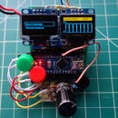
Step 8: Testing the Circuit


First step to building it is to test the circuit on a breadboard. This is where you can make changes as needed, and modify the component values. Power it with 3.7V since that is going to be the actual use condition.
Everything worked fine for me so I went ahead to the next step.
Step 9:


Ordering the PCB (files provided later in the Instructable) will make your life a lot easier and simpler. Having to make all the Ground and Power connections, and every connections manually using wires is quite a task. If you have the mental fortitude and impatience as well as the desire to save on the shipping costs, then buckle up and pull out the perfboard. Make it a small board to be even more bold.
The board should not be bigger than 82 X 62 mm, since that is the size of the PCB I designed the case for.
Anyway, place down the IC sockets for your IC so you don't fry them trying to solder them. If you do fry them, you can replace them without having to throw away the board or your sanity.
Use long wires to connect the LDR, LED, PIR sensor and the switch to the board. The Solar cell also has to be connected with a long wire. All of these are going to be mounted to the casing, so they can't be soldered to the board.
It took me an hour to solder it all, and 7 more to find the little mistakes.
Better luck to you.
Step 10: 3d Modelling and Printing


I started the 3d Modelling around the size of the PCB. The idea was to have removable parts for the top of the case and the front of the case. The LED, and the PIR sensor can be mounted to the front plate, which will slide onto the body of the case, and the roof will lock on top the case. There will be hole on the side for the LDR, and one hole on the back for the toggle switch.
The bottom of the Case would have an extension to attach two more arms, which will finally connect to a base plate which will be mounted on the wall. The arms will be tightened to each other using nuts and screws that will also be 3d Printed.
I printed everything on a Monoprice Select Mini V2 printer, and the print space is pretty small. So I had to print one item diagonally to fit. The print was done with 20% infill, and I believe the print layer were 0.219 mm. I tried printing the screws and nuts with support and without support. They came out much cleaner and the threads were much better without support. However if your print starts to sag just reduce the Nozzle temperature a little so the layers dry quicker.
I had issues with spacing, so I printed with 87% scale for the screw and 95% scale for the nut to get them to fit nicely on the threads. Your mileage may vary.
Step 11: Assembly


I mounted the LED and PIR sensor onto the front panel using super glue. Then I mounted the solar cell to the Case roof using super glue. I slid the circuit board into the case and then glued the LDR and switch in place. Finally I put in epoxy to make it water proof and closed off the case. I then added the arms and tightened them using screws.
All that was left was to mount the build. I screwed the mounting plate on top of our door, and then attached the arm to the mounting plate.
I could finally sit back and relax and wait for night time.
Step 12: Files for the Project
The different STL files to print the 3d Parts are all here. I had issues uploading the Gerber files through the Instructable Editor, so I just included a link of it to my google drive: Gerber File


Step 13: Troubleshooting and Final Words

If you are having trouble with any part of the project feel free to comment here and I will try to answer them as I can. The circuit is very forgiving and can be troubleshooted using a multimeter for most part. If the LED doesn't light up at any stage check the output voltage, and then go backwards from there until you reach the Battery. Somewhere along the way you will find the mistake.
Keep an eye on the power supply if you are using one, or have a multimeter in the current measuring mode to make sure you are not frying up the battery or draining it.
This is pretty simple of a build, but who knows how far some of you can take it? Maybe even build your own actual video monitoring system with camera modules and a microcontroller alongside the solar power? Would love to see if any of you attempt to build this.
Anyway, thank you for reading or watching or skimming or skipping the Instructable.
Here is a picture of my pumpkin and cucumber plant to end the Instructable.
See you on the next one.

Runner Up in the
Digital Fabrication Student Design Challenge


