

Introduction: Squiduino- Arduino Based Squid Game RED LIGHT GREEN LIGHT Project


Netflix's Squid Game series is very popular. The RED LIGHT GREEN LIGHT(RLGL) game shown in the series is also very popular. This project resembles most of the things of the RLGL game. It also features a few things that were not shown in the series. I made this project for my 5 years old daughter who watched a cartoon of Squid Game. She demanded a toy that could rotate the scary doll and play the 'RED LIGHT' and 'GREEN LIGHT' sounds. I decided to design a toy that could resemble most of the things from the series like timer, moving doll, etc. and I used Peppa Pig toys to recreate the scene of Squid game. It is now available for everyone to buy at buildcircuit.com
I named it SQUIDUINO(a combination of Squid Game and Arduino), this project is sold in fully assembled form and as a DIY kit.
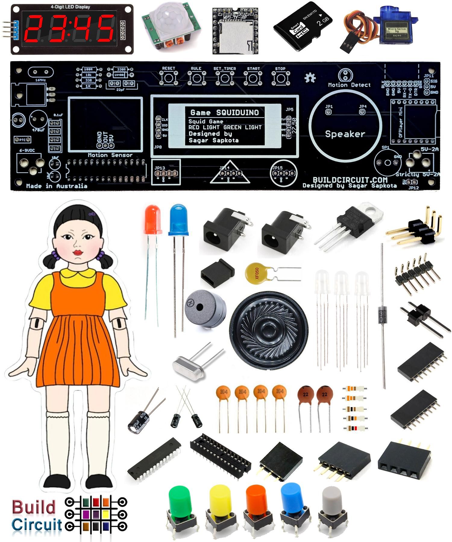
I redesigned this DIY Arduino kit to build this project. The major parts of SQUIDUINO are:
- PIR Motion sensor
- MP3 player with 2GB microSD card. The 2GB microSD card comes with 8 sounds to give you a feel of Squid Game. Download the sounds here: With Gunshot and With Guitar
- 0.56″ TM1637 display module working as a countdown timer
- SG90 Servo
Other supporting components are:
- Buzzer
- 3 x RGB Common cathode LEDs
- 8 Ohm Speaker
- Buttons
The device is fully programmable, you will need an FTDI basic breakout board to program it. You can use the Arduino IDE software to program the kit.
Features similar to Squid Game Series
- The doll rotates.
- It plays RED LIGHT and GREEN LIGHT Sounds in a random manner. Also plays several other sounds that remind us of the Squid Game series.
- Detects motion. It is not so accurate because I have used a basic PIR motion sensor. Therefore, the circuit cannot specifically tell which player moved.
- It plays the rule of the game.
- It has a timer.
Additional features:
- There are 3 RGB LEDs that turn RED when the circuit plays RED LIGHT sound and turn GREEN when the circuit plays GREEN LIGHT sound
- The three RGB LEDs are inside circle, triangle, and square which are the most notable shapes seen in the series.
- The timer can be set for 1:00 - 5:00 minutes.
Supplies


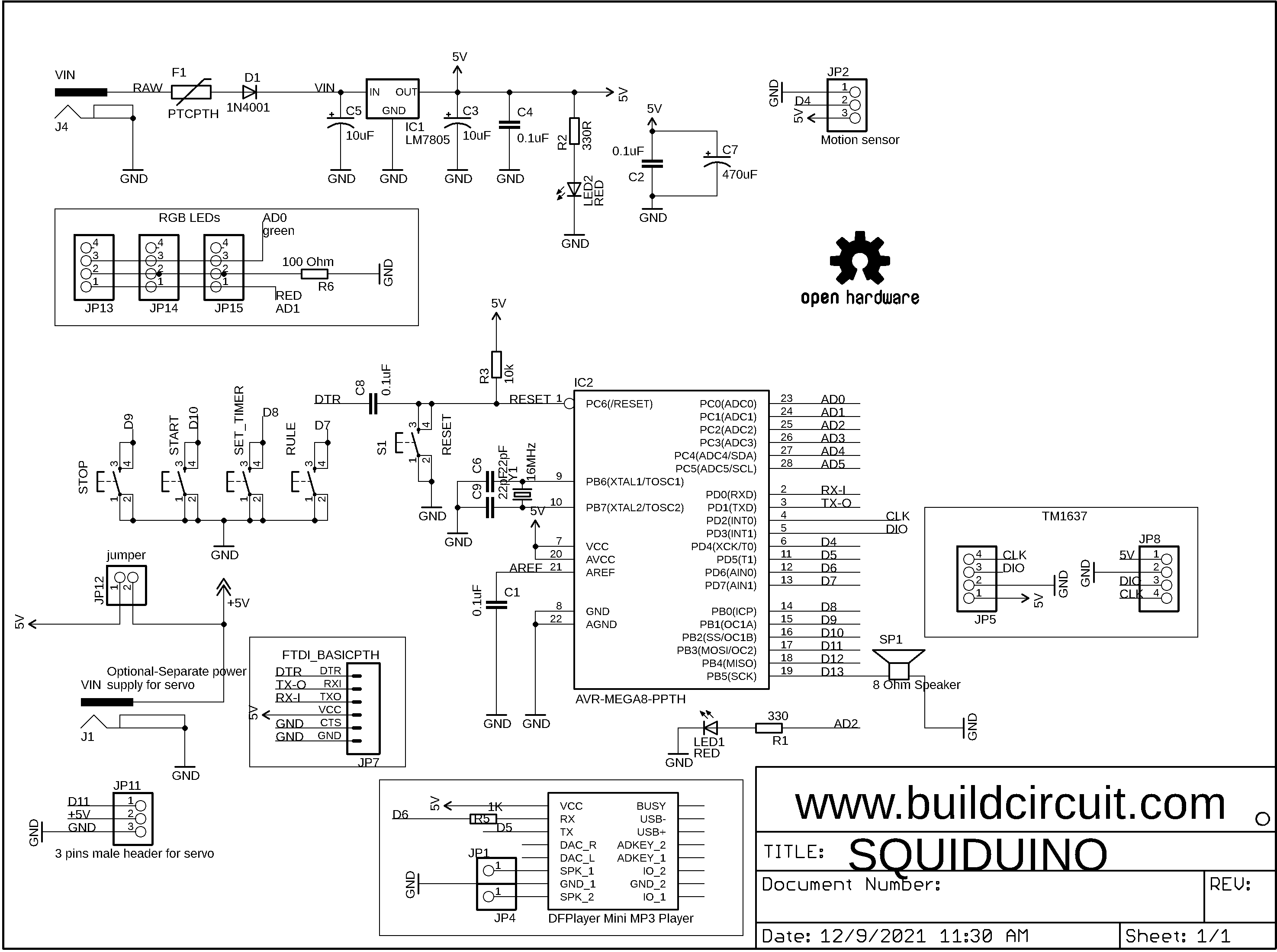
If you design your own PCB, you will need these components and if you decide to make it using Arduino UNO, you need to buy the components shown on the wiring diagram, you can also see the schematic.
Arduino users need to buy these components:
- Arduino UNO
- DFPlayer-mp3 player
- Motion Sensor
- 8 Ohm Speaker
- TM1637 module- If you are using Arduino UNO, you need to use v1.2 TM1637 module. I have programmed for both 0.56" TM1637 display and the V1.2 module. The Arduino Sketch used for 0.56" module does not work for the other one.
- 1 x BLUE LED(used as motion detection indicator )
- 3 x Common cathode RGB LED
- 4 x tactile switches/buttons used for Start, Stop, Rule, and Set Timer functions
- 1 x Buzzer (It is played after the timer reaches 00:00)
- 1 x SG90 Servo
- 1 x 1K Ohm resistor
- 1 x 220 Ohm resistor
- 1 x 100 to 220 Ohm resistor to connect to RGB LED
- 1 x 2G to 8GB microSD card(this is used to store the mp3 files)
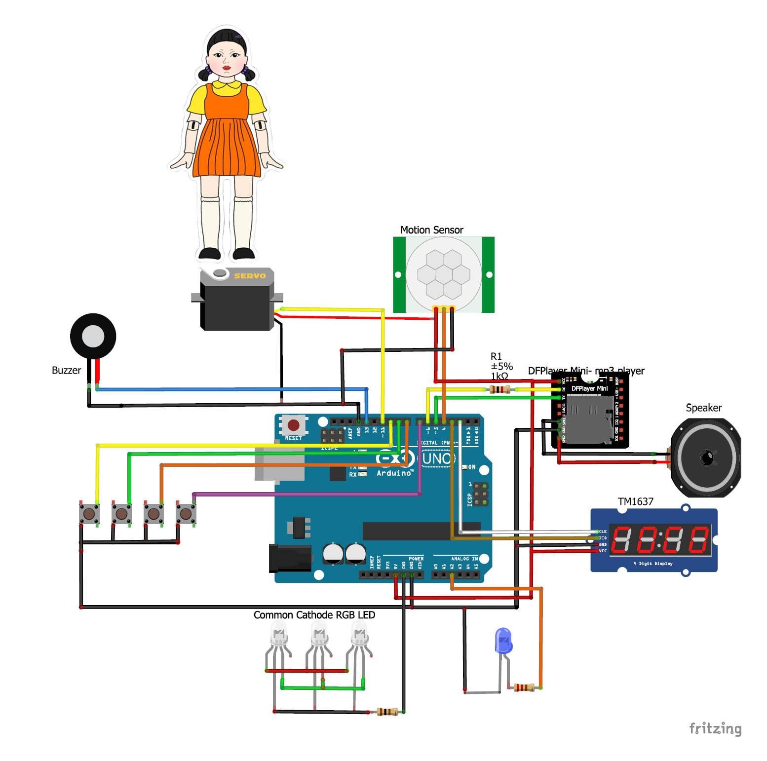
Step 1: Connect All the Modules and Components to Arduino


Connect all the modules and components to your Arduino as shown on the wiring diagram.
Please bear in mind these points:
- As mentioned earlier, you need to use v1.2 TM1637 for this project because the Arduino sketch shared on Instructables is written for this module. Note that v1.2 module uses TM1637Display library.
- The servo draws a lot current, so, if your Arduino is interrupted while the servo is moving, you will have to use a separate power supply for the servo only. In that case, you will need a 5V-1A power supply(DO NOT EXCEED 5V). Connect GND wire of servo to GND and 5V wire to 5V of the power supply and connect D11 of Arduino to data wire of the servo. So, make sure that you use one power supply for Arduino, either use a USB cable OR use a 5V to 9V power supply and connect it to the DC barrel of Arduino and use another 5V-1A supply for servo.
Step 2: Download Arduino Libraries and Sketch
The Arduino Sketch shared on Instructables has been coded for V1.2 TM1637 module. v1.2 module uses TM1637Display library. This does not work for 0.56" TM1637 module. However, the PCB I have designed is for 0.56" module.
Supporting libraries:
When you download the Arduino Sketch Folder, you will see 6 files. You need to open squidGame.ino, which will open all other 5 files.
If you download the Arduino Sketches separately, put all the files into one folder and open squidGame.ino.

Step 3: Download the Sound Files and Copy Them to Your MicroSD Card

You can download sound files from these links:
- Sound files with gunshot sound.
- Sound Files with Guitar Sound- Some users may not want to play gunshot sound.
Copy the mp3 folder into your MicroSD card. Please make sure the files are inside mp3 folder.
Step 4: Print the Doll and Stick It to a Cardboard and Glue It on Top of the Servo


You can print the image and stick it to a cardboard and glue it on top of the servo. You may also use other toys.
Step 5: Play the RED LIGHT GREEN LIGHT Game
There are 5 buttons used in this project.
- Reset: Reset button resets Arduino.
- Stop: Stop button also works like the reset button. It stops the game and takes the circuit to its default state. The button has been kept there just in case any user wants to use it for another purpose.
- Start: Start button starts the game. As soon as the button is pressed, the countdown timer starts and plays sound in random intervals.
- Rule: Rule switch is used for playing the rule of the game
- Set Timer: This button is used to set the timer from 1:00 minute to 5:00 minutes.


