

Introduction: Tact: Low-cost, Advanced Prosthetic Hand


In this instructable I'll show you how to make Tact, a low-cost, open-source prosthetic hand. Tact exceeds other open-source prosthetic hand models in several ways: it costs only $100 for all components ($250 to also add myoelectric control), can be assembled using only one hand and a clamp, achieves the same performance as current $30k-40k commercial prosthetic hands, and when used with myoelectric (muscle) control can easily perform several different grasps such as fine pinch, three-jaw chuck, power grip, etc. These claims are discussed in detail on the next step. Watch it in action!
In this instructable I will show you what components are needed, how to print the hand, how to assemble it, and make several suggestions on how to control it.
Step 1: Performance Comparison


Tact vs Commercial Devices
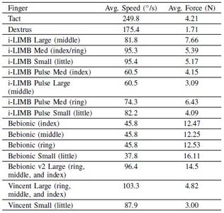
As stated previously Tact performs the same as $30k-40k commercial prosthetic hands and is an improvement over other open-source hands. In the first chart above you can see a motor comparison made between Tact and i-Limb (expensive commercial device). By knowing the performance of the motors in the i-Limb a careful motor selection was made to find one that output the same power as the commercial device but at less cost. This allowed our hand to apply forces at the fingertip within the range of the $30k-40k hands, shown in the second table. We also see that Tact has a much higher speed than the commercial devices this has been cited in prosthetics studies to be desired for easier grasping of objects in daily tasks, it also allows us to possibly gear down the input further and produce more output. In the last table a general set of size and weight specifications show that Tact is the same size as the other devices and in fact much lighter due to 3D-printing.
Tact vs Open-Source Devices
In all these comparisons we see Tact applies roughly 2.5x the force of the comparable open-source Dextrus hand while weighing 20% less and having roughly half the palm thickness. These are much more desirable features for a prosthetic user to have. In addition, the last image demonstrates the four-bar linkage in a finger of Tact. This linkage ensures that the two joints of the finger close proportionally and reliable each time the hand is operated, providing consistent performance. Most open-source designs such as Dextrus only use a tendon strung through the finger to winch it close. This results in awkward and jerky movements as random joints close at different times, especially when gripping objects.
Trade-offs
While from these descriptions Tact may seem at a serious advantage to all other hands we have made several trade-offs to achieve these results. The biggest being the weakness of the 3D printed parts and mechanical operation. Compared with the rugged injection molding and metal gearing of commercial myoelectric hands, the Tact is much more easily damaged (but also repaired). In addition the lack of non-backdriveable gearing makes the hand less energy efficient as power must be drained continuously when holding items.
Step 2: Parts List


As discussed in the intro, this hand was designed to be made using common off-the-shelf-components and 3D-printing. In the images above you can find a complete list of all parts needed and either vendors or part numbers for each component. Due to shifting online listings I haven't supplied specific links, but a basic search should find all components. Don't be afraid to substitute parts for things on hand!
In addition to the listed a few tools are required: phillips or flat head screw driver (depends on your type of screws), two needle nose pliers, superglue, and wire cutters.
For the 3D-printed components a Makerbot Replicator 2X was used, but any 3D-printer is capable of making these components. If you don't have access to any, consider using a company such as Shapeways that will take files submitted online and mail you printed parts. All STL files needed to make the Tact hand parts can be found on the dedicated Github page. For those new to Github I recommend reading through a basic tutorial.
I printed all components except for the spool at a resolution of 0.2 mm (200 microns) and 10% infill. This helps prints to be made more quickly while still strong enough. The spool should be printed at the finest resolution and highest infill that your printing device can produce. Total printing time for me took around 14 hours. Once you have all your parts ordered and 3D-printed components, you are ready to assemble!
Step 3: Finger Assembly


All fingers including the thumb follow the same basic assembly structure and use the same components. When assembling check each step (one paragraph per) with the pictures ordered above. In the Github page I've also included another pdf of assembly instructions so you can refer to that if stuck.
1. First take your length of steel cable, tie a knot at one end, and dot it with glue to ensure it doesn't slip. Take the spool and pull the cable through the smaller hole by the top of the part so that it starts on the outside diameter of the spool and pokes out on the inside of the spool diameter. Now pull the rest of the cable through until just the knot is left at the outside of the hole. Send the free end of the cable through the larger hole in the spool, beginning on the inside the diameter of the spool and exiting to the outer edge of the spool.
2. Take a motor and press fit the spool onto the shaft of the motor. Ensure that you have lined up the flat part of the motor shaft with the flat part of the spool. If this is not aligned correctly you risk damaging the spool.
3. Now take the motor housing piece. Insert two 6mm M2 screws into the small holes on either side of the larger opening. Push the motor/spool combination up through this larger hole and screw in the motor to the housing.
4. Gather both the finger tip part and the linkage. Using an 12mm M2 screw and nut fasten the linkage into the slot in the finger tip part. Make sure it is loose enough to still rotate freely.
5. Now take the lower portion of the finger and slide the linkage and finger combination inside of it. Watch the orientation. Screw the two finger pieces together through the remaining hole in the finger tip part with a 20mm M2 screw.
6. Take the partially assembled motor housing and finger parts and affix the free end of the linkage to the appropriate hole in the motor housing using a 12mm M2 screw. You will have to bend the finger fully to be able to do this.
7. Now affix the remaining hole in the lower portion of the finger to the remaining hole in the motor housing using a 20mm M2 screw.
8. Now route the length of cable remaining out of the inside of the motor housing and up through the hole in the cylindrical part of the lower finger piece. Take a wire crimp or tie a knot in the steel cable and add a dot of glue for strength. Use the wire cutters to clip excess cable.
9. Repeat this finger assembly process for all fingers and the thumb. Note that the thumb has a different finger tip piece but the rest remains the exact same. Once all the fingers are assembled, take both hand parts and lay them flat. Note that one has 4 holes. This is the back plate of the hand. Line up all the motors in this part and affix each one to the back plate using a 6mm M2 screw. Then take the front plate and affix it to the two appropriate fingers with 6mm M2 screws.
I've updated the CAD files for the prosthetic hand. Please leave feed
Attachments

Step 4: Thumb Assembly


1. To assemble the completed thumb finger to the body of the hand, first find the servo and the servo holder printed piece. They should press fit together.
2. Next take the small part that mounts between the servo and the thumb and attach it to the corresponding hole in the thumb piece using a 6mm M2 screw.
3. Now assemble the thumb bracket onto the servo using the two screws given with the thumb servo. Attach this assembly onto the front part of the hand containing the other four fingers with two 6mm M2 screws.
You have completed the mechanical build of the hand!
Step 5: Controlling the Hand

Typically advanced prosthetic devices use myoelectric control to read the small voltages given off by a user's muscles, called electromyography (or EMG) signals. From these voltages we can tell what muscles around the users forearm are flexed and can then determine what grip they are using. This requires a complex 8 channel EMG chip and the use of a machine learning algorithm called linear discriminant analysis. While I hope to provide an instructable for this in the future, since this approach requires a lot of prior knowledge in electronics and computer science I will propose a couple ways to control this hand more simply.
Single channel EMG boards that are already set up for easy use with microcontrollers such as an arduino are produced by a company called Advancer Technologies. The boards they sell are both cheap and have many tutorials for setting them up. In fact this company has several instructables showing exactly how to apply this to control objects. I strongly recommend you check out their products and 'ibles to get the hand up and moving.
Another method for the people who are interested in computer science would be to make a PID controller, or simpler PI/P/PD control method along with switches or buttons to move the hands to different positions.
In another alternative method you could use voice control as I've demonstrated how to get working with another open-source robotic hand design.
Best of luck on building the device and I hope it gets to those who need it!

Grand Prize in the
3D Printing Contest

Participated in the
Mind for Design

Participated in the
Move It


