

Introduction: Tesla GPS Speedometer Pod, Powered From the Car Wireless Phone Charger Pad.


The Tesla Model 3 is known for having a minimalist interior with all information on a central tablet computer type display. While done to reduce build time and so cost, many owners would prefer at least a speed display in front of the steering wheel rather than at the top corner of the central screen.
Aftermarket Tesla-specific devices exist to do this but they are very expensive, for example one steering column mounted display resembling a pair of Mickey Mouse ears is around $500.
In this project, which costs around $30(!), I used
- A very low cost digital display that comes in an neat hemispherical pod.
- It contains its own GPS satellite sensor and so all you need is to supply power and it will work.
How to supply the power neatly?
- It is powered automatically from the wireless phone charging pad of the centre console of the car giving a very neat solution without USB cables all over the place.
I didn't want unsightly USB cables running around to the centre console, then through the sliding top door of this console to plug into the fiddly micro-USB sockets located inside. Apart from looking messy and rendering the console lid unable to fully close, the sockets would soon become damaged plugging/unplugging in a USB cable repeatedly.
The experiment here was to see if the speedo module could be powered from one of the two wireless mobile phone charger panels just under the main car display screen (it can). If so, this means to power the speedo display all you need to do is place the power coil (attached to a phone-shaped slab of plastic) onto the charger pad, and when done, remove it slightly - easy and simple to do. No plugs, no switches, neat wiring (hidden in air vent).
Supplies


Things you need:
1) Generic GPS speedometer display. There are several types but the one I used has a round binnacle (see images).
2) 1 metre long micro USB extension cable, i.e. micro-USB male at the end connecting into the speedo module and female micro-USB at the other end into which the wireless power receiver coil will plug. This cable will run inside the air vent and then down behind the central screen so you end up with a very neat result.
3) A wireless mobile phone power receiver coil. These are made to stick to the back or, or even go inside the case, of older phones that do not have wireless charging built into them. They have a short ribbon cable with, typically, a micro-USB plug on the end which must be carefully curved around and plugged into the micro-USB socket on the base of the phone. They are quite fragile.
4) Clear tape such as Kapton tape. Any adhesive tape would be OK though.
5) I 3D printed a structure to hold the speedo module so it can simply be clipped into the horizontal air vents without damaging them. Alternatively the speedo module comes with a self-adhesive pad. You could probably even use Blu-Tack as the module weighs very little.
6) Small file or even better a Dremel with a cutting disc.
7) A drill for small holes for small cable ties e.g. 3mm
8) Four small cable ties.
9) Magnifying glass to read the instruction leaflet that comes with the Speedo module. For some reason the font is incredibly small.
Step 1: Decide How You Would Like to Mount the Speedo Binnacle

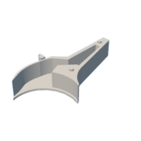
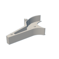
I glued the binnacle to a 3D printed holder. This holder gently clips into the air vents as shown. As the binnacle is so light it will not move around as you drive.
Step 2: 3D Printed Holder

Here are the parts. The .stl files you need are also attached.


Step 3: Prepare Female End of Extension Cable

The plug on the wireless power receiver coil is very small and flimsy. To get it to insert into extension cable correctly you need file or very carefully grind away the plastic so the end of the metal part of the female micro-USB socket on end of the extension cable is protruding with no rim of plastic in the way that might stop the plug on the end of the receiver coil being inserted fully. Insert the two together when you have done this.
Step 4: Plug Them Together

Plug power coil and female and of extension lead together. This is very fragile so we will now make a plastic, or wood, or anything else non-metallic phone-sized slab to mount all this to so the coil and its fragile connections are well mounted and protected form any damage. Here I am using a 6mm thick piece of plastic sheet. It needs to be heavy enough to keep itself planted firmly against the charging pad in the car while you are driving.
Step 5: Dimensions of the Phone-shaped Object

Cut your slab of wood, acrylic or whatever else to these dimensions.
Step 6: Cable Ties

Drill holes as shown to allow cable ties to run through the plastic to hold the cable really firmly on the other side. File (or use dremel with cutting disk) grooves to take the cable ties so the backs of the ties do not project above surface of the plastic as shown - because the receiver coil is going to need to lay flat on this side of the plastic slab later on.
File a wide slot as shown in end of the plastic to take the ribbon cable from the receiver coil as it curves around from one side of the plastic slab (where the coil is) to the other side, where the extension cable and plug-connection are located and held in place with the cable ties.
Use very small cable ties.
Step 7: Sticky Plastic Film

Apply adhesive plastic film or tape as shown here then ideally wrap it over the base of the plastic slab phone substitute, so it runs up the other side, also then holding in place the receiver coil. This is quite tricky to do neatly. Notice how the end of the plastic has been filed to allow the ribbon cable to curve around and plug into the end of the extension cable without too much undue stress being applied to this very fragile assembly.
Step 8: Stick Down the Receiver Coil

Wrap the adhesive film around so it also then holds the receiver coil in place.
Step 9: Glue the 3D Printed Mounting to the Speedo Binnacle

I used hot gun glue. First test fit everything in the car, make sure the display is pointing at you and not at the floor, when you are sitting in the car. Hold the parts together with Blu-Tack or similar until you can permanently glue them later on.
Step 10: Glue Parts Together

Here I have Blue-tacked them in place ready for using a hot glue gun inside to hold binnacle to the 3D printed part.
Step 11: Glue in Cable

Here I glued the cable so it emerges from side of the binnacle well recessed into the air vent, so you can then run it along inside the air vent without it wanting to fall straight back out. I also have a 3D printed insert (not shown) that can be used to fill this gap once cable glued in place.
Step 12: Plug Cable Into Back of Binnacle Before You Glue Anything Together!

This may be obvious but you must plug male end of micro-USB extension lead into socket in rear of the speedo module and test fit everything before you start using glue !
Step 13: How to Turn It on and Off

Turn it off by NOT placing the coil on the charging pad in the car.
Step 14: Turning on and Off

To turn display on you just place your imaginary phone onto the charging pad of the car. The cable (see earlier photos) can be run along to the speedo display inside the upper ventilation slot so you cannot see it.
NOTE: I also earlier include a 3D print file for a cover which runs over the cable seen here on the back of the red panel which makes it look nicer and gives you something to grip when you are placing and unplacing it on the charger pad.
Also:
I assumed when I parked the car the charger pad would automatically turn itself off so the speedo would just come on and off automatically when you drove the car. This does not seem to be the case, when I exited the car and locked it the pad carried on powering up the imaginary phone. So, to turn off the speedo you do need to just move it slightly away from the charger pad when you park the car. This is still way easier than plugging USB extension cables in and out of fiddly sockets, it is neat and it keeps the main centre console unobstructed by any wires.
Step 15: Cover for the Cable

Step 16: Enjoy!

It seems to work very well.


