

Introduction: The Hemlock Electric Bike - a Commuter's Dream E-bike - Designed Using Tinkercad and Fusion360!


I wanted to share my latest ebike design with the Instructables community. Although, this bike is completely different compared to previous bikes I have built it is still 100% based on what I have determined to be the most important aspects of a good electric bike for commuting long(ish) distances. Some things to look forward to with this Instructable are:
- A specially designed, Arduino based computer system and 3D printed case
- How to program and use a Kelly Controller for a 52V e-bike system
- A specially designed, Arduino based rear lighting system with flashers and turn signals
- And much much more!
I am not going to go through everything in minute steps, but I should give you enough meat to get an idea on how to complete each task. I will include all STL files for 3D prints, all Arduino codes for the builds, and some additional tips and ideas to help you build a bike similar to this.
For you number hungry techies out there, here are some quick specs on the main build:
- 52V system using a rear hub motor and a Kelly KBSX controller
- KBSX controller can safely pull a continuous 45 amps and can handle bursts of 100 amps
- Range with mild pedaling is about 20 - 25 miles (depending on terrain). I can go 20+ miles moving at 25 mph in our very hilly central Massachusetts area
Supplies
Step 1: From Old to New - a Great Frame Deserves a Second Chance


Maybe you saw one of my other electric bike postings. I had built this great electric commuter bike from old Ford C-Max batteries, then changed it, and changed it again, and again, and again once more. I loved the frame, and the bike was great too, but it was time to really join the big leagues. I really loved the frame I was using but wanted a bigger battery, more powerful motor and controller combo, and wanted to really increase the bike's carrying capacity. I ended up finding an inexpensive, but excellent, bike on Craigslist which I used as a donor bike to migrate all of my current components over to. This way, as I built my new bike I would still have a bike to commute to work with (with gas on the rise it's nice to save a tank per week!). Once my frame was stripped of all of the components I used some Soy Gel stripper to remove all of the paint and then used a wire wheel on my angle grinder to remove any remaining paint.
Step 2: Down to the Bare Metal


I stripped the entire frame, including the suspension fork, down to the bare metal to prep the bike for a paint job in my buddy's shop. He is a auto body teacher at a local technical high school and he thought that this project would be a great small job for a few of his students.
Step 3: Prototyping


One of the main reasons I wanted to build a bigger, faster, more stable machine was to help deliver my wife's breads for her business (www.brynnesbread.com). I wanted something that I could still load up with all of my work stuff along with any breads / baked goods my wife needed delivered to the local stores and cafes. I decided to use some foam board to help me prototype some ideas. This was a great idea because it allowed me to see right away that I DID NOT want to have a massive rack on the back of the bike. I was originally thinking of making the bike similar to a long-tailed bike, but then quickly decided that a more conventional rack would be just fine for my purposes. No matter what, this is a great practice in engineering and design!
Step 4: Racks and Kickstand Plate


I really wanted my bike to be extremely versatile. Capable of carrying all sorts of loads on both the front and back of the bike. I ended up settling on a typical long-bed rear pannier rack that I had available in the shop. I then purchased an Origin8 Messenger rack for the front of the bike. This was a hefty expense but I really wanted something lightweight, robust (it can hold 55 pounds), and versatile. I have used it a number of times and I can honestly say that I am very happy with the purchase. Before the bike was to be painted I decided to make a legit kickstand plate out of some plate steel. I love using the motorcycle-like center kickstands but the clamps on these things have a tendency to dig into your frame. After having one mounted to this frame for seven years there was noticeable damage to the frame. I figured the best was to remedy this was to make a solid steel plate that the kickstand could butt up against. It was Tig welded to the frame after the appropriate holes were drilled in it for the fixing bolt to pass through for the center-mount kickstand.
Step 5: Checking the Handlebars and Taping Off


I decided to use some unique handlebars for this new rig. I wanted the bike to be a bit more upright and comfortable for commuting long distances. I also wanted a bit more cockpit space to put all of the necessary components I wanted to include for the electric bike aspect of this commuter bike. I ended up buying the Surly Sunrise handlebars along with a new stem that properly fit the handlebars. A bit more of an added expense but my current stem was cracked between the bolts and the previous handlebars were way too narrow to fit everything comfortably. After checking that the handlebars and wheels fit the rig nicely I was ready to disassemble completely and tape everything off for painting. The fork was fully disassembled and all slides and non-painted surfaces were sealed up with painters tape. The frame was also prepped completely and sealed up where I didn't want any paint sneaking by. I decided to leave on the rear rack and the towing hitch so they could both be painted at the same time while on the bike. I wanted something that was reminiscent of a hemlock tree for the colors. A moderately bright green was chosen to represent the new growth of the needles on the tree and a fade to black to represent the dark, aged bark found on ancient hemlocks. I think the results came out pretty dang sharp!
Step 6: Rebuilding the Front Suspension


Since I had the front suspension completely apart I decided to take the time to clean it completely and rebuild it. Amazingly, after 20+ years and 8,000 miles, all of the seals were still good and the springs were still healthy. I decided to lubricate the entire thing and reassemble it. It works good as new now!
Step 7: The Kit


I didn't go too crazy with the electric bike kit. I wanted something reliable and capable of pulling 2,000 watts continuously, but that could also handle a little more (say 3,000 plus watts) when I wanted to zip around. I opted for a 52v lithium ion battery with a 20 amp hour capacity and a Voilamart rear wheel kit. These rear hub motor kits can handle a wide range of voltages and current levels. Your weak link is going to be the motor controller, and in this case it was definitely my weak link. The motor controller was supposed to be able to pull 35 amps but it never exceeded 27 amps during my first tests.
Step 8: First Tests


I decided to use an expandable half-frame bike bag manufactured by Serfas to hold all of the wiring, the shunt (for the ammeter), the switch, and all other small components that needed to be housed safely. This worked great and kept things both neat and sleek looking. I used the same meter I use for all of my electric machines, the Bayite Power Meter. You can check out more details on how to wire this with my previous Instructable.
At this point the bike looked pretty slick and overall the ride was good, but not what I really wanted. The controller, as mentioned in the previous step, just wasn't cutting it. The bike had little to no pick up or torque and the efficiency of the controller seemed to be below what the bike was capable of. The beauty of prototyping and testing like this is that it gives you time to really think through what aspects are most important with your design. Winter was coming and I knew I would have plenty of time to continue this design and build the bike exactly to the specs I wanted.
Step 9: Quick Note on the Power Meter Shunt


I wanted to give you a quick note on the shunt for this bike. I did it a bit differently compared to my previous bike (and as shown in that Instructable). I knew I would be changing things up from the stock controller and I didn't want to lock myself into a box by soldering all of the connections to each other and then shrink wrapping those connections. That would make for a difficult mess to deal with when I changed things up. I opted for using XT60 connectors for the shunt so that I could easily connect and disconnect the power meter. I drilled a hole in the supplied bolts so that the ends of the wires could pass through them and I could tighten things down neatly. I then connected the XT60s to the ends that would lead from the battery and the ends that would lead to the motor. A simple solution that would make things immensely easy in the future!
Step 10: Enter the Kelly Controller


Kelly Controllers makes some fantastic electric vehicle controllers for a pretty affordable price. They are rock solid controllers and the KBS-X mini is particularly remarkable in the fact that it is so small yet can handle such high currents. I bought the 48v 40 amp KBS-X mini since it can handle up to 60v and bursts of 100 amps. This fit perfectly with my battery set up. There were a few things that had to be changed (as expected) when I wired up the Kelly controller. For one, I needed to wire up a pre-charge resistor for the controller to help pre-charge the capacitors in the controller. This prevents frying the caps due to the inrush of current. I also had to tinker around with the hall effect wires and sense wires until I found a combination that was suitable for my specific motor. I would go into more detail on this but it really is motor-specific. I found the video I have linked here to be extremely helpful with the wiring but if you have any specific questions I would be more than happy to answer them. My best advice is to make sure to label all of your wires completely and to the best of your ability using the manual that comes with the controller.
I mounted the controller directly to the frame using a section of plastic pipe and some zip ties. I wanted to keep the controller out in the open as much as possible to keep it cool. I opted for the waterproof controller kit so there is no worries about shorting due to moisture. You'll notice that there is a switch on there... let's talk about that fiasco.
Step 11: Switching Up the Switches


I am making a few edits to this section due to the requests of a few readers. I was very unhappy with the solenoid I was using and it seemed to be more of a headache to find something that properly fit the bill, that is what drove me to the switch. I have now put over 400 miles on the switch and have checked it on multiple occasions. I have not seen any signs of arching, overheating, melting, or anything that would make me worried about its integrity. I have removed my "power is power" statement because I agree that this was an incorrect assumption to make and I want to make sure everyone is safe. I will continue to monitor my switch and if I see anything remotely close to an issue I will swap to a solenoid with this switch. It shouldn't be too tough to utilize the switch as one side to pre-charge the caps and the other side to act as the coil actuator for a high current solenoid. I will update things as they progress but at the moment, and with large current draws, I have not seen one single problem.
I had originally thought that using a solenoid would be my best bet to start the bike without causing any arching. I ordered a decent solenoid and keyed switch from Amazon, wired up the pre-charge resistor along with a diode (as instructed by Kelly Controllers) to the solenoid and got things running fine. The problem was that the solenoid was heating up while it had current running through it. Although it was rated for specific voltage I was passing through it, it apparently wasn't manufactured to the best standards and couldn't handle the high current and voltage combination. Additionally, it was bulky, loud, and just didn't seem to fit the build. After a number of trials I decided I needed something more streamlined and neater. I returned the other parts and then I found a large three-way switch that fit the bill perfectly! This switch is an AC switch used to select between two different machines. It is rated for 690V at 25A. That means that this switch can handle almost 18,000 watts! I wanted a three way switch since I wanted one side to pre-charge the controller and one side to fully charge the controller.
I used a hot nail to melt a small hole into my bag so that I could pass the stem of the switch through the bag. I then used the pre-charge resistor / diode combination and wired that in on one side of the switch and the power on the other. When I turn the switch to the left it pre-charges at 9.5v and when I turn it to the right it allows the full power of the battery to be at the ready for the controller.
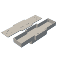
Step 12: Front Computer and Display - Designed Using Fusion360


I really wanted to make this bike 100% ready for big rides and I wanted all of the information to be right up front and clear for the rider. There were plenty of displays available for e-bikes but I really wanted mine to have information that most of the displays did not provide. I wanted to have speed, location, current, voltage, power, time, date, and more available at a glance. I decided that the best way to do this would be to make my own system. I used Fusion360 to do the design for the case for the computer system. I wanted the display to include the Bayite power meter and a LCD with a gps module. I found some code that I was able to modify (see attached) using an Arduino Leonardo as my microcontroller. I used a Ublox neo-6m gps unit with a 2.8" TFT LCD display shield and the Leonardo. Everything has loaded up great but I am still having trouble with the gps latching on to satellites... this is something I am going to have to tinker with or just completely change. Although I love the idea of the GPS I am leaning towards making this display show the physical speed with a new design. Everything can easily be disassembled and a single wire could be added as a sense wire for a magnetic speedometer system.
Nonetheless, I added a few switches to this computer display. One switch powers on the Arduino (for both the front computer and rear lighting system), another turns on the front light (I'll show you that in a bit), and the final switch turns on the blinking lights for the rear lighting system (more details next step). There is a three way rocker switch that is set up for a future speed limiter on the bike. The controller already has a Low-Normal-Boost ability, and I have run those wires up from the controller and to the computer system. I just need to finish the programming.
Before 3D printing the case for this computer system I decided to use a cardboard box to prototype things and see how I would like them to appear and work. Like I said earlier, prototyping is awesome!
I have included the code I used for the speedometer with gps along with the STL files for the dashboard I designed on Fusion360. There is a slit in the design that allows for a piece of plexiglas to slide in and cover the entire front display and protect it from moisture and impact. I haven't installed it yet since I am still tinkering with the design.


Step 13: Rear Lighting System


I teach a course called Engineering Principles and one of the challenges I gave my students was to design a rear lighting system for my new bike. I challenged them to first use Tinkercad to create a working system utilizing a 555 timer and then to physically build the system on a breadboard to test its functionality. They did an awesome job with this assignment and each student produced a unique take on the lighting system. I included the document with this step if you are interested in doing a similar assignment in your own classes. Tinkercad is an amazing resource for my class since it allows students to first prototype their projects in the digital world before they make the electronics produce the magic smoke in the real world. I decided to take some of their ideas and utilize them in my own rear lighting system. One big difference is that I decided to use an Arduino nano as my platform instead of a 555 timer. This wasn't really because it was more practical but because I wanted the lighting system to be expandable and I wanted more practice with writing code for Arduino and this was a perfect opportunity.
I prototyped my design on breadboards and then soldered up the entire thing on perf boards. I used Tinkercad to do my own prototyping and you can find the design here if you wanted to check out how the system works.
I once again designed the case on Fusion360 and I have included the STL files for your use. The switches were simple momentary switches that I installed at easy access on the handlebars. I used a scrap piece of aluminum hexagon stock and made a mounting plate for the switches, which was directly attached to the brake lever's bolt. This makes easy access with my non-throttle hand to push the left or right turn signal. I used an old 1990's cable with eight wires in it as my switch and power wires. This had to be run from the rear rack all the way up to the main computer on the handlebars. Power for both the front computer and the rear lighting system was provided by the 12V output on the Kelly Controller.
I know that there are a lot more details I can provide but I thought that a summary would be more beneficial for the masses. If you have specific questions please don't hesitate to ask and I will help you out.

Step 14: The Hemlock Badge


I have this thought that maybe I could build bikes like this for folks in my area. Something very different from what you can buy pre-built, a bit more boutique and a bit more personalized. This bike has been amazing for commuting to work and I love how zippy it is. I really wanted to put the finishing touch on the machine and since my mother makes jewelry using metal clay I thought she might be able to make me a copper badge with a Hemlock branch at the forefront. She used copper metal clay to make the badge and made the hemlock branch and cone by a direct impression she made in a form first. She then pushed the copper clay into that form and fit everything around a dowel I turned that was the same diameter as my bike's head tube. After firing the metal clay she cleaned it up and put a clear coat on it. If I was to start a small business making bikes like this I would like to have a personalized badge on each bike because it really did come out great!
Step 15: Some Quick Odds and Ends


I really wanted this bike to be an all weather machine so I purchased pannier bags that could carry my computer, work goods, and anything else without getting damaged by rain, snow, or splashing. I was super impressed with the quality of these Rhinowalk bags and they have held up great for the first 400 miles of riding.
I had to drill a passage hole for the front derailleur in my kickstand plate. Just keep this in mind if you decide to do something similar as I did. My derailleur cable came from the bottom up so I had to have this hole to allow for the movement of the cable. I was able to use a dremel with a burr bit on it.
I mounted an ultra bright LED light originally on the top of the bike's handlebars, which looked ridiculous. I was able to move the light so it sat nicely between the cross braces on the handlebars (as seen in the final pics). Just be careful with the positioning of the lights since you can blind on coming traffic and you will surely get pulled over by the police.
Finally, I use Luna Cycle's smart charger so that I can keep my battery running for longer. I typically don't charge past 90% and always charge at 1 to 2 amps to minimize battery degradation.
Step 16: The Final Thoughts

There are so many details that I did not include with this Instructable. I know that ultimately this is a complex, long-winded project and if you are interested in any aspects you will surely ask for help or look for guidance. I am more than happy to help you out and give you some tips. I hope that this project inspires you to try some new ideas and to build something that is truly remarkable.
This bike has been amazing and I absolutely love riding into work each day. For a few pennies I can travel 14 miles to work while enjoying the beautiful world around me. Have a good one and enjoy the ride!

Grand Prize in the
Bicycle Speed Challenge


