

Introduction: The Most Comprehensive Guide to Programming the AT24C32 / AT24C64


I love tutorials that DIYers put online. They save so much time, and can make tackling new projects a little less intimidating and easy to comprehend. The problem I continue to run into however is the fact that no one seems to want to take the time to explain how their code or circuit actually works. They're pretty much just like if your setup isn't exactly like mine, than good luck figuring out how to use this code that I put 4 comments on.
What I'm here to do is change that. I want to explain the deeper level concepts, so that when it comes time for you to customize the code to your applications, you have a great starting place. So if you're interested in how this code actually works, put down your TV remote and get ready for long tutorial.
What I cover:
Datasheet Portion:
- How to read and understand the AT24 (or other I2C device) datasheet
- Determine device address from datasheet
- How the memory is organized
- How the address rollover works
- How to organize a data packet based on datasheet. We thoroughly examine the packet structure outlined in the datasheet and use that information to construct our data packet.
- Understand what an 8 bit address really means
Arduino Coding Portion:
- How to write the Arduino code with a line by line walkthrough
- How to split a 12-bit address across 2 bytes
- How to understand these lines Wire.write(byte >> 8); & Wire.write(byte & 0xFF);
- How the Arduino Wire library works from the functions to the start, stop, and ACK bits.
Supplies
Wiring one of these modules is super easy! There are plenty of other tutorials showing you how to connect it all up. Since it's an I2C device, the only connections are:
- 5V
- GND
- SDA (with 2.2K pullup to 5V)
- SCL (with 2.2K pullup to 5V)
Step 1: Reference Material
For Reference:
- Figure numbers correspond with the AT24CXX datasheet
- Annotations refer to my uploaded images for easy explanations
- The module that I'm using a DS3231 AT24C32 IIC RTC Module Clock. I'm not going to bother posting a link because it is a Chinese-made module and they can be found just about anywhere by typing in that description. It's obviously a DS3231 clock module with an AT24C32 EEPROM module included on a nice PCB with a battery holder.
- Every time I reference bits, they will be 0-indexed, just like our code is. This standard will keep us from having any confusion about which bit I'm referring to.
- This tutorial is not for absolute beginners; You'll need to do some studying and get a good foundational understanding of I2C communication, the Arduino Wire Library, binary, and bit shifting. You can find links to references below. There are also plenty of excellent tutorials online about these topics taught by folks much more knowledgeable than myself. If you are a beginner, these concepts are not to terribly complicated. Give yourself a week and get studied up!
- How I2C Works
- Arduino Wire Library Functions
- Arduino Wire Library In-Depth
- Bitshift operators
- Binary/DEC/HEX conversion chart
- RapidTables to convert from Hex/Dec/Binary. It's extremely useful. For the purposes of this tutorial, you will need to use the Dec->Binary converter, not the all in one converter. The AIO converter takes a number like 4095 and separates it into two bytes (16bits). For our purposes, we just want to convert the decimal number into as many bits as it takes 4095 -> 111111111111.
Step 2: Device Addressing
As most good projects begin, we are going to start by studying the AT24Cxx datasheet. I just want to make a quick note: If you are trying to understand how to use a device, you are going to need to put some quality time in with the datasheet. I've read this datasheet over and over, and somehow I kept on missing very important bits of information. It is helpful to know what to look for yes, but also don't slack on the datasheet studying.
Device Addressing:
This device has 3 configurable address pins, A0, A1, and A2. If we take a look at Figure 1 we can see which bits they are referring to.
Figure 1:

"These pins can be configured high or low to change the device's actual address to add up to 8 AT24xxs on the same I2C line." You can see by the binary table below in the green columns how we can configure the AT24Cxx hardware to add up to 8 different device addresses. Remember, everything we talk about is zero-indexed.

The datasheet continues, "These bits must compare to their corresponding hardwired input pins. The A0, A1, and A2 pins use an internal proprietary circuit that biases them to a logic low condition if the pins are allowed to float." i.e. if the pin is LOW, the corresponding bit needs to be low and vice versa.
Let's take a look at the hardware. Based on the board I bought, I can tell that pins A0, A1, and A2 are pulled up to VCC through 4.7K resistors, meaning that their corresponding bits will need to be high. I found this out by probing the circuit board with my multimeter in continuity mode. It looks like this:

Also we cannot forget this small line in the datasheet: Page 9 says, "The device address word consists of a mandatory one, zero sequence for the first four most significant bits as shown." With this information, we can determine what our address is. Simply start with the mandatory sequence, 1010 and add the 3 high bits from A0, A1, and A2. Our address is going to be 01010111 which when put into a binary to hex calculator it equals 0x57.
Now here is something that is very important. If you're like me, you studied up on how I2C works, and you know that I2C only uses 7- or 10-bit addresses, so why does the datasheet keep saying "8-bit address"? This is technically incorrect terminology. There's one sentence on page 9 that took me 15 reads to finally see, "The eighth bit of the device address is the read/write operation select bit." Okay so instead of calling it a 7-bit address like everyone else, they call it an 8-bit because they are including the R/W bit. Thanks for following standard terminology! This means that we can only use the 7 highest bits of the device address byte for the device address.
Step 3: Memory Addressing & Organization
The AT24C32 can store up to 4096 bytes of data (AT24C64 = 8192 bytes). It has a 12 bit memory addressing system while the AT24C64 has a 13 bit address. We are going to focus on the 32K version for now. In order to write/read from a specific place in memory, we are going to need to send a 12-bit address. Why 12 bits? Well remember we have 4096 "slots" of memory. That last slot has a decimal address of 4095, NOT 4096, because it's zero-indexed. If we convert 4095 to binary, we get 111111111111. You can see that is 12 bits which corresponds with our 12-bit addressing system! Since I2C communicates only 1 byte at a time, we're going to have to split this 12 bit address up over two different bytes. We'll get into the coding portion of that a bit later.
Note: For the AT24C64, the last byte has a decimal address of 8191. This converts to 1111111111111 which is 13 ones. The datasheet says that this 13th 1 will go into the 4th bit of the first word address byte, see Figure 2.
It is also very important to understand how the AT24Cxx organizes data, or else me might not be able to read/write to the chip properly. Page 3 of the datasheet tells us: "The 32K/64K is internally organized as 256 pages of 32 bytes each. Random word addressing requires a 12/13 bit data word address." This is incorrect for the 32K version. There are only 128 possible pages of 32 bytes to equal 4096 bytes (128 * 32 = 4096). Page 9 continues, "The data word address lower 5 bits are internally incremented following the receipt of each data word. The higher data word address bits are not incremented, retaining the memory page row location. When the word address, internally generated, reaches the page boundary, the following byte is placed at the beginning of the same page. If more than 32 data words are transmitted to the EEPROM, the data word address will “rollover” and previous data will be overwritten."
We are essentially splitting the 12-bit address into 7 high bits (rows) and 5 low bits (row position). If we plug 7 bits into a binary calculator, we can see that we can achieve a maximum value of 127, which correlates to our 128 rows. Similarly, 5 bits can equal a maximum number of 31, or our 32 bytes within the row. Upon receipt of each data byte, the AT24Cxx will increment the address we initially sent it by 1. Since it's only incrementing the lower 5 bits, it's only going to increment up to row position 31. Once we reach 31, it will rollover to the beginning of that row with byte position 0. You may be beginning to see a little bit of problem here. Let's grab some visuals to help us understand this. In this photo you can see our rows and our columns highlighted in blue, which each cell filled with their corresponding decimal positional values.
Annotation 1:

In the photo above, if we want to write 6 bytes of data starting with byte address 74, everything is hunkey dorey. However, what happens if we write that same 6 bytes of data starting with byte address 93? Once the AT24Cxx sees that we get to the end of the row, it rolls over to the beginning of the row and writes the remaining three bytes in the beginning of that row. This can be confusing as we might think the last 3 bytes of our 6 byte packet would have gone into addresses 96, 97, & 98. That write rollover issue would look like this:
Annotation 2:

It is very important to note that the above rollover is a "write condition rollover". To add even more confusion, you might think that the page read function also rolls over to the beginning of the page we were reading from because of the exact same wordage being used, Page 10: "When the memory address limit is reached, the data word address will “roll over” and the sequential read will continue." This sound EXACTLY like our write rollover however it is not the same. To understand what is happening for the "read rollover" condition, we have to read the current read address paragraph on page 10. "The internal data word address counter maintains the last address accessed during the last read or write operation, incremented by one ... The address “rollover” during read is from the last byte of the last memory page, to the first byte of the first page. The address “roll over” during write is from the last byte of the current page to the first byte of the same page. Here it describes the differences between the "read" and the "write" rollover conditions.
I did a little experimenting here to verify this. The first line in the serial monitor Annotation 3 shows that I wrote 6 bytes to the EEPROM starting at address 93 just as shown in Annotation 2. All bytes were successfully written as shown by line 2 in the serial monitor. I then did a sequential read starting at address 93, and in line 3 of the serial monitor, you can see that the first three bytes match the first three bytes written, but the last three are "wrong"! This is because our sequential read function increments the entire address, not just the row address like the write function. In fact, the values returned were not blank but the actual addresses of those bytes, being 96, 97, & 98. In line 4 of the serial monitor, I performed a new read function on addresses 64, 65, and 66, and you can see that the remainder of my byte packet was written there due to the write rollover.
Annotation 3:

In Summary:
The bytes are organized into 128 pages/rows of 32 bytes each. The automatically incremented write address rollover is row based, and the read function rollovers at the last byte of the entire amount of available bytes, byte 4095.
Step 4: The Byte Write Data Packet
Let's figure out what exactly we need to send to read and write 1 byte to the AT24Cxx.
Byte Write:
Our example values are:
- Device Address = HEX0x57, BIN01010111
- Byte write location = DEC4095, BIN111111111111
- Data byte = HEX0x3E, BIN00111110
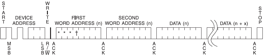
Let's start with the most basic write. Take a look at Figure 2 to see how we need to organize our data packet.
Figure 2:

- Device Address & R/W bit: Our address is 0x57 or in binary, 01010111. Remember we can only send 8 bits at a time. We have a small problem because the lowest bit of the first device address byte is the R/W bit. How do we deal with this? Notice our address, 01010111. If you're familiar with binary, the MSB (most significant bit) here is a zero. We don't need the MSB to show the number 0x57, we only need the lowest 7 bits to do that. We can simply chop off the MSB and use 7 bits for our address, 1010111. Note, the highest number that you can make with 7 bits is decimal 127 or HEX 0x7F. Since we are not using the MSB in our address byte, we can bitshift everything to the left by 1 bit, leaving a free "spot" for our R/W bit. Bit shifting is literally shifting bits by a desired amount, in our case 1 bit to the left. So 01010111 << 1 becomes 10101110. The AT24Cxx knows that are only using the 7 highest bits for the address, so it knows that 10101110 is 0x57. We understand this to be true because in Figure 2, they show the 7th bit of the device address packet as MSB and the 1st bit as LSB, with the 0th bit being the R/W bit. (remember, I'm using 0-indexed numbers). The 0th bit R/W is set to 0 indicating a write to the AT24Cxx.
- Byte Address: (Don't confuse this with device address!) Let's address the 4096th byte of the AT24C32's memory (the last byte) so we can see how the split 12-bit address works. Remember the 4096th byte is going to be addressed with the number 4095 (the last time I'll call attention to 0-indexing!). If we convert 4095 to binary, we get 111111111111. Looking at Figure 2, you can see how the first 4 bits of our 12 bit address go into the lowest bits of the first word address byte, and the remaining 8 bits go into the second word address byte. What about the highest 4 bits of the first word address? The 4th highest bits of the first word address are "don't care" bits for the AT24C32. We can write ones or zeros to those bits as it does not matter, as our address is only 12 bits, with our MSB being in the 3rd (or 4th for 64K) bit of the first word address. In my annotation, the AT24C32's MSB is in bold, and the AT24C64's MSB is regular font. I left them as the stars and cross for reference as they don't matter.
- Data: Now all we need to do is send one byte of data over that we want to EEPROM to store! Our example byte is HEX0x3E or BIN00111110. Let's take a look at what our packet will look like:
Annotation 1:

Hopefully by now you understand where all the bits go and what they mean. Let's focus our attention now on how to read from the device.
Step 5: The Read Byte Data Packet
Scrolling along in the datasheet brings us to this figure for reading a singular byte from the EEPROM. Thankfully this is very similar to our write function, so it won't be too hard at all to add it to our coding toolbox.
Figure 5:

You at first might be tempted to use the "Current Address" read function which would be absolutely whopper, but sadly it's not very helpful for reading the byte we just wrote. Here's what the datasheet has to say for itself: "The internal data word address counter maintains the last address accessed during the last read or write operation, incremented by one." Keyword being incremented by one, so we can't use that function to read the byte we just wrote. I'm sure this function has its uses, but I'm just not seeing it right now!
Let's start by reading page 10 of the datasheet: "RANDOM READ: A random read requires a “dummy” byte write sequence to load in the data word address. Once the device address word and data word address are clocked in and acknowledged by the EEPROM, the microcontroller must generate another start condition. The microcontroller now initiates a current address read by sending a device address with the read/write select bit high. The EEPROM acknowledges the device address and serially clocks out the data word. The microcontroller does not respond with a zero but does generate a following stop condition (refer to Figure 5). Righttt... let's see if we can make that easier to understand. Here are the steps we need to follow in order to read a byte from a specific address:
- Send a device address with the R/W bit set to WRITE as before
- Send the two-byte word address of the data byte we want to read from
- Once we receive an ACK bit from the AT24Cxx, send another I2C start condition.
- Send device address again, this time however with the R/W bit set to READ. The AT24Cxx will first send an ACK condition, then proceed to shoot us over our requested byte.
If these start/stop/ack bits don't make a lot of sense, don't worry! Not only does the Arduino I2C library handle all this for us, but we are going to cover that in the page write section of this tutorial. I thought it would be a little easier to explain it then.
What is our data byte going to look like? Once again we'll use our example variables, excluding the data packet:
- Device "Write" Address Packet = HEX0x57, BIN10101110 (R/W bit set to WRITE)
- Byte write location = DEC4095, BIN111111111111
- Device "Read" Address Packet = HEX0x57, BIN10101111 (R/W bit set to READ)
- Incoming data byte = HEX0x3E, BIN00111110
Note: The second send of the device address packet is being sent with the R/W bit set to READ.
Annotation 2:

Alrighty! That sums up the singular bit write and read portion of the AT24Cxx datasheet. Now let's figure out the Arduino coding portion to begin saving data!
Step 6: Writing the Arduino Code for Byte Write/Read
If you've made it this far, props to you! This won't take too much longer I promise. Alright let's dive in. We'll start by taking a look at the most basic write/read code example and going through it line by line.
#include <Wire.h>           // include wire library
byte i2c_address = 0x57;    // AT24Cxx device address
int bAddress = 4095;        // Address of the byte we want to write to
byte dataByte = 0x3E;       // byte we want to write to memory


void setup()
{
  Serial.begin(9600);       // Start serial coms


  Wire.begin(i2c_address);  // Start wire library with our address
                            // only needs to be called once in setup


  Wire.beginTransmission(i2c_address);    // begin communication with our AT24Cxx
  Wire.write(bAddress >> 8);              // write MSB or highest address bits
  Wire.write(bAddress & 0xFF);            // write LSB or lowest address bits
  Wire.write(dataByte);                   // write 1 data byte to AT24xx
  Serial.print("Write status = ");
  Serial.println(Wire.endTransmission()); // end transmission and print write status


  delay(10);   // wait 10ms for EEPROM to write our packet to memory


  Wire.beginTransmission(i2c_address);    // begin communication with our AT24Cxx
  Wire.write(bAddress >> 8);              // write MSB or highest address bits
  Wire.write(bAddress & 0xFF);            // write LSB or lowest address bits
  Wire.endTransmission();                 // end transmission
  Wire.requestFrom(i2c_address, 1);       // we want 1 byte from said device address
  byte rcvData = Wire.read();             // read the byte from AT24Cxx into rcvData
  Serial.print("Byte read = 0x");
  Serial.println(rcvData, HEX);           // print out HEX value of byte

}


void loop()
{
  // Arduino you deserve a break!
}
1) It's very important to note, beginTransmission() and write() are slightly misleading terms, they do NOT send commands/packets to the I2C device. They are simply queuing commands, which means they are adding bytes to an internal buffer in the Wire/TWI library. This internal buffer is not sent to the device until end.Transmission() is called! Once end.Transmission() is called, it will begin to send the data out to the I2C device using the necessary I2C protocols. Read the in-depth article linked above for more information. You can also stick around and I'll explain it further towards the end of this article.
2) To start, we include the wire library and declare a few variables. This part is pretty self-explanatory.
#include <Wire.h>           // include wire library
byte i2c_address = 0x57;    // AT24Cxx device address
int bAddress = 4095;        // Address of the byte we want to write to
byte dataByte = 0x3E;       // byte we want to write to memory
3) Wire.begin(i2c_address); sets up the Arduino hardware for communication with an I2C device. This only needs to be called once in the void setup().
4) Wire.beginTransmission(i2c_address); This function accepts a 7 bit address and sets the R/W bit to 0 or WRITE. If an 8-bit address is passed in (like our 1-byte address, 0x57) the highest bit is truncated (deleted). Basically, the byte is bit shifted to the left by one bit (byte << 1), and the lowest bit is set to 0 (WRITE). Our address packet is 0x57 or 01010111 becomes 10101110.
5) Wire.write(bAddress >> 8); Remember how we needed to split up our 12-bit address into two bytes? What's happening here? bAddress is the address of the byte we wish to write to in EEPROM. Earlier, we declared this variable as an int with a value of 4095. The datatype int is a 2-byte value. Let's enable the x-ray and see what that looks like in binary:

You can see we have a high byte and a low byte that make up int bAddress. When we call the function wire.write(value);, write only sends 1 byte, the lower byte. You might already be able to see the problem. Our first word address needs to contain 4 high "don't care" bits, and the lower 4 bits of the first word address needs to contain the higher 4 bits of our 12 bit address. So how do we do this? We bit shift everything to the right by 8 bits using bit shifting: bAddress >> 8. With the x-ray back on, we see this:

Since we shifted bAddress to the right by 8 bits, the 8 lower bits are "shifted out of existence" as indicated by red. The lower byte of int bAddress shown in green now has the 4 "don't care" bits, and the 4 higher bits of our 12 bit address. Wire.write will be sending the lower 8 bits shown in green of int bAddress.
6) Wire.write(bAddress & 0xFF); writes the lower 8 bits of our 12 bit address bAddress. How does it do that? & is a bitwise AND operator. If you remember, it compares two bits and only if both bits are 1, the resulting output is 1. If we AND bAddress with 0xFF(11111111), it will look like this:

You can see how 0xFF is only 8 bits, and it's being AND'd against the lower byte of bAddress. The resulting operation leaves us with just whatever is left in the lower byte of bAddress indicated in green. Once again, write will only send the lower byte. Breathe easy now, the hardest part is over!
7) Wire.write(dataByte); Send our data byte, 0x3E.
8) Serial.print(Wire.endTransmission());This command sends the entire buffer out to the AT24Cxx, taking care of all the necessary I2C communication protocol jazz. Wire.endTranmission() returns a value from 0 to 4, indicating the status of the write. 0 = transmission okay, so we are just going to print that out to the serial monitor just to verify that our packet got sent successfully!
9) delay(10); From page 9 of the datasheet, "Following receipt of the 8-bit data word, the EEPROM will output a zero and the addressing device, such as a microcontroller, must terminate the write sequence with a stop condition. At this time the EEPROM enters an internally-timed write cycle, tWR, to the nonvolatile memory. All inputs are disabled during this write cycle and the EEPROM will not respond until the write is complete." On page 5 tWR (Write Cycle Time) is defined as having a maximum time of 10ms, so let's give it second to catch its breath before we start shouting at it again!
10) Let's start all over again! In order to read, we are going to write our "dummy" packet, which is exactly the same as the first three lines of our write data packet. Instead of writing a data byte however, we are just going to send that information out with endTransmission().
  Wire.beginTransmission(i2c_address);    // begin communication with our AT24xx
  Wire.write(bAddress >> 8);              // write MSB or highest address bits
  Wire.write(bAddress & 0xFF);            // write LSB or lowest address bits
  Wire.endTransmission();                 // end transmission
11) Wire.requestFrom(i2c_address, 1); Very similar to how beginTransmission() works. This function accepts a 7 bit address and sets the R/W bit to 1 or READ. If an 8-bit address is passed in (like our 1-byte address, 0x57) the highest bit is truncated (deleted). Basically, the byte is bit shifted to the left by one bit (byte << 1), and the lowest bit is set to 1 (READ). Our address packet is 0x57 or 01010111 becomes 10101111. Additionally, we are going to tell the wire library that we only want to read 1 byte of data. This also configures the necessary NACK and STOP bits for the end of the read cycle (after 1 byte is read).
12) byte rcvData = Wire.read(); Set byte rcvData to the byte that is being read from the AT24Cxx.
13) Serial.println(rcvData, HEX); Print out the byte that we just received from the AT24Cxx in HEX! It should match the byte we initially wrote, which was 0x3E. *Note, when using Serial.print(value, HEX);, it does not add the 0x prefix to the byte. For readability purposes, I added this 0x in the serial print statement right above this line.
14) Upload! Let's see if it works!

Step 7: Page Write
As promised, I will show you how to perform a page write/read function and how the Arduino Wire/TWI library handles all the necessary I2C communication protocols. We need to keep in mind that we have those aforementioned rollovers, so keep in mind how many bytes you are writing to what addresses.
Page 9, Page Write:A page write is initiated the same way as a byte write, but the microcontroller does not send a stop condition after the first data word is clocked in. Instead, after the EEPROM acknowledges receipt of the first data word, the microcontroller can transmit up to 31 more data words. The EEPROM will respond with a zero after each data word received. The microcontroller must terminate the page write sequence with a stop condition (refer to Figure 3).
Figure 3:
Explained with words, that will look like this:
- Send start condition and the slave address with the R/W bit set to WRITE (Wire.beginTransmission does this for us as explained earlier)
- Wait for an acknowledge
- Send the first word address
- Wait for ACK
- Send second word address
- Wait for ACK
- Send one byte of data
- Wait for ACK
- Repeat steps 8 & 9 until we are ready to stop sending bytes or we've reached our 32 byte limit
- Send STOP condition
Right so how do we create all these conditions? Thankfully, the Arduino library handles everything for us. We we call Wire.endTransmission, the Wire/TWI library handles the start bit, sends all the bytes in the queue waiting for an ACK bit after each byte, then finishes the entire communication with a stop bit. Pretty handy right? So in order to do a page write, all we have to do is queue more bytes of data with Wire.write, and Wire.endTransmission will continue to send our queued bytes 1 by 1 after each ACK bit comes back. Remember, the AT24Cxx is incrementing our original byte address by 1 after each received byte. This will happen until 32 bytes have been written. This could rollover, so you need to be careful of that! To write 4 bytes to the chip, that would look like this:
  Wire.beginTransmission(i2c_address);    // begin communication with our AT24Cxx
  Wire.write(bAddress >> 8);              // queue MSB or highest address bits
  Wire.write(bAddress & 0xFF);            // queue LSB or lowest address bits
  Wire.write(dataByte);                   // queue first data byte to AT24xx
  Wire.write(dataByte);                   // queue second data byte to AT24xx
  Wire.write(dataByte);                   // queue third data byte to AT24xx
  Wire.write(dataByte);                   // queue fourth data byte to AT24xx
  Serial.print("Write status = ");
  Serial.println(Wire.endTransmission()); // end transmission (write all the bytes, handle I2C coms) and print status of write.
This of course is not the best way to send multiple bytes of data; don't worry I'll cover that in the last part of the tutorial!
Step 8: Sequential Read
Page 10, Sequential Read:Sequential reads are initiated by either a current address read or a random address read. After the microcontroller receives a data word, it responds with an acknowledge. As long as the EEPROM receives an acknowledge, it will continue to increment the data word address and serially clock out sequential data words. When the memory address limit is reached, the data word address will “roll over” and the sequential read will continue. The sequential read operation is terminated when the microcontroller does not respond with a zero but does generate a following stop condition (refer to Figure 6).
Figure 6:
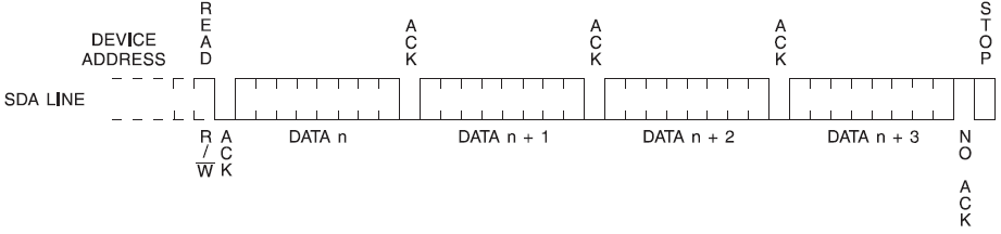
Explained with words, that will look like this:
- Send start condition and the slave address with the R/W bit set to WRITE (Wire.beginTransmission does this for us as explained earlier)
- Wait for an acknowledge
- Send the first word address
- Wait for ACK
- Send second word address
- Wait for ACK
- Send another start condition and the slave address with the R/W bit set to READ (Wire.requestFrom does this for us as explained earlier)
- Wait for ACK
- Receive the byte of data from the AT24cxx
- Send ACK to AT24cxx
- Repeat steps 9 & 10 until we are finished reading as many bytes as we want to
- Send a NACK. This tells the AT24cxx to stop sending us data
- Send a STOP condition to end communication.
And how do we go about that with code?
  //// Dummy write
  Wire.beginTransmission(i2c_address);    // begin communication with our AT24Cxx
  Wire.write(bAddress >> 8);              // write MSB or highest address bits
  Wire.write(bAddress & 0xFF);            // write LSB or lowest address bits
  Wire.endTransmission();                 // end transmission
  ///// End Dummy write


  Wire.requestFrom(i2c_address, 4);       // we want 1 byte from said device address
  rcvByte = Wire.read();
Wire.requestFrom(i2c_address, amountOfBytesToRead); is the real workhorse of this library! It sends the start condition with the address, setting the R/W bit to read. Waits for ACK, then it reads incoming byte from the AT24Cxx. It sends the AT24Cxx another ACK. Since we told the function that we want to read 4 bytes, it will read 3 bytes, sending an ACK to the AT24Cxx after each byte, but on the 4th byte after it is read, it sends a NACK. This tells the AT24Cxx that we no longer wish to keep reading from it. Our function then sends a STOP bit to end communication. All of the bytes read go into an internal buffer that the Wire/TWI library handles. Wire.read(); retrieves those bytes from the internal buffer for us.
You might be wondering, if we do rcvData = Wire.read(); and there's 4 bytes to be read, rcvData isn't an array! Yes, it's currently just a byte and it will get overwritten with each new byte it reads. We will take care of that in the code below.
Step 9: Sequential Write / Read Code
#include <Wire.h>           // include wire library
byte i2c_address = 0x57;    // AT24Cxx device address
int bAddress = 64;        // Address of the byte we want to write to

byte dataByte[] = { 0, 1, 2, 3, 4, 5 }; // create an array of 6 bytes to send to the EEPROM

int packetSize = sizeof(dataByte); // calculate how bytes are in the array dataByte

void setup()
{
  Serial.begin(9600);                       // Start serial coms

  Wire.begin(i2c_address);                  // Start wire library with our address
                                            // only needs to be called once in setup

  Wire.beginTransmission(i2c_address);      // begin communication with our AT24Cxx
  Wire.write(bAddress >> 8);                // write MSB or highest address bits
  Wire.write(bAddress & 0xFF);              // write LSB or lowest address bits

  for (int i = 0; i < packetSize; i++)      // initiate a loop will happens as many times as packetSize
    {
      Wire.write(dataByte[i]);              // sequentially write byte after byte
    }

  Serial.println();
  Serial.print("Write status = ");
  Serial.println(Wire.endTransmission());   // end transmission and print write status

  delay(10);   // wait 10ms for EEPROM to write our packet to memory

  Wire.beginTransmission(i2c_address);      // begin communication with our AT24Cxx
  Wire.write(bAddress >> 8);                // write MSB or highest address bits
  Wire.write(bAddress & 0xFF);              // write LSB or lowest address bits
  Wire.endTransmission();                   // end transmission

  Wire.requestFrom(i2c_address, packetSize);// we want x amount of bytes from said device address
  byte rcvData[packetSize];                 // create a byte array to store incoming bytes
  int byteCount = 0;                        // variable to increment when inside our while loop below

  while (Wire.available() > 0)              // while there are bytes to be read, perform the loop
    {
      rcvData[byteCount] = Wire.read();     // read byte from buffer into rcvData (index 0)
      Serial.print("0x");
      Serial.print(rcvData[byteCount], DEC);
      Serial.print(", ");
      byteCount++;                          // increment our index # to write to next slot in array
    }

}


void loop()
{
  // Arduino you deserve a break!
}


I'm going to skip over the stuff we already explained in the code earlier and just cover the newer code.

1) byte dataByte[] = { 0, 1, 2, 3, 4, 5 }; creates a byte array of 6 bytes. As these are singular bytes or 8 bits, the largest number we can achieve per byte is 255. If we want to store larger numbers, we would have to split the larger number up across 2 or more bytes.

2) int packetSize = sizeof(dataByte); is an handy function that returns the size of an array. Since our array is 6 bytes, packetSize will = 6. We don't want to declare a static variable for the packet size and I think you'll see why later on without me explaining.

3) I'm skipping over the I2C setup.

4) The code below creates a loop. It will iterate as many times as the size of our byte array. Arrays just like everything else are zero indexed, so to write index 0 of the array, we have to start with i = 0. We now iterate 5 more times until i is equal to 5. This sends out the last byte of our byte array. Now i = 6 which is NOT less than packetSize, so we kick out of the loop and move on. We also use i to send the appropriate index position of our array with Wire.write(dataByte[i]); . This way we can write each byte of the array to the internal buffer queuing them up for end.Transmisssion().

for (int i = 0; i < packetSize; i++)      // initiate a loop will happens as many times as packetSize
    {
      Wire.write(dataByte[i]);              // sequentially write byte after byte
    }


5) I'll skip over the dummy write, see above if your forgot.

6) Wire.requestFrom(i2c_address, packetSize); So requestFrom will take our address and set the R/W bit to READ, and then we tell it how many bytes we want to read. We want to read 6 bytes which is how many bytes we initially wrote, which is the size of packetSize.

7) while (Wire.available() > 0) will hold us in it's braces until all 6 packets have been read. We use byteCount to increment our array rcvData so that we can read all 6 bytes into it.

int byteCount = 0;
while (Wire.available() > 0)              // while there are bytes to be read, perform the loop
    {
      rcvData[byteCount] = Wire.read();     // read byte from buffer into rcvData (index 0)
      Serial.print("0x");
      Serial.print(rcvData[byteCount], DEC);
      Serial.print(", ");
      byteCount++;                          // increment our index # to write to next slot in array
    }
And there you go!
Step 10: Conclusion
I really hope you found this tutorial insightful, and inspired you to set out to use that I2C device that you couldn't find a pre-written library for. I was not able to find any tutorials that walked you through what the I2C code and what it actually does. I had to squeeze out of page 7 on a random Arduino forum that wire.beginTransmission(); truncates the address's MSB and adds a 0 R/W bit to your address! The Arduino Wire library makes a lot of this stuff quite easy for you, the documentation online is just not as easy and straightforward as I like it to be. I spent an entire week of learning binary, studying the Arduino Wire library, banging my head over the AT24xx datasheet, and learning about random things that I saw in different libraries that had no real applications to my uses. Don't expect to learn everything in one day; it will take hard work, but you can do it! I want to instill in my DIY/Programmer peers that COPYING AND PASTING CODE YOU DON'T UNDERSTAND DOESN'T TEACH YOU ANYTHING. If you copy/paste code, sure it might get your project up and running, but this teaches you absolutely nothing. Isn't there some old fishing fable about teaching vs having it done for you :).
The code I wrote above isn't gospel; there are some best practices you may want to implement like error handling, multi-byte page write/read, data rollover, and other goodly bits. What I wrote is to give you a good baseline to teach you how the I2C library works, and a practical example from the datasheet of a device.
If you have any questions, comments, or suggestions, please drop them below! I love hearing feedback on how I helped you out or how I could improve anything from my code, teaching method, visuals, and more.
See you in the next one!


