

Introduction: The Scariest, Arduino-powered, Flashing and Screaming Halloween Pumpkin!


Here's an instructable to an afternoon project that just had to be done: a flashing, screaming, arduino-powered halloween pumpkin. It's a lot of fun, involves a tiny bit of soldering and is great for learning about sensors and light output via neopixels.
We've assembled it over an our, most parts just connect with the jumper cables. The NeoPixel Ring requires a bit of soldering.
Here's what you need:
- a pumkin, we got one of medium size. If you buy a bigger one, the loudspeaker and usb power pack might just fit right in, which is a plus
- a usb power pack, anyone is really fine
- a powered loudspeaker with 3.5mm jack, like a JamBox
- a BareConductive touchboard
- a NeoPixel ring, I chose a 12x ring, 1 1000uF capacitor and a 470Ohm resistor
- a Ultrasonic Distance Sensor, HC-SR04 or similar
- some jumper cables, again cheap on eBay
Ok, let's begin the journey by cutting the pumpkin!

Step 1: Create the Pumpkin and Find Scary Mp3s!

This step is really reasy, I assume you have a knife and some cutting skills. Just remember that you have to place the ultrasonic distance sensor somewhere. It is not ideal to have it touch the soft and moisty walls of the pumpkin, so I created a relatively big mouth that is able to hold the distance sensor. The rest is "common halloween pumpkin procedure".
If you have younger kids in the family, maybe part of the family wants to work on the pumpkin while the older ones take care of electronics.
You also need to find some scary laughter - and save it to the microSD card of the touchboard. We found great sound effects here. Be sure to save them to the microSD card using Track names like Track001.mp3, Track002.mp3. The code on the arduino-powered Touchboard later on requires the Tracknames to be in the mentioned format. Plug the SD card back in, maybe do a quick test with the default firmware of the touchboard.
So let's move on to soldering the NeoPixel ring which is used for the light effects!
Step 2: Prepare the NeoPixel Ring for the Light Effects


The NeoPixel ring is powered directly by the 5V Pin of the Bareconductive Touchboard. That might not be a super wise decision, but for a small 12pixel ring, the power the 5V pin is able to bring seems enough. For larger rings, you might want to add a seperate power supply.
To safe some space, I soldered the capacitor directly to the ring - make sure the negative side goes to GND and the positive one to where the 5V power is connected. Also, to make things a bit safer for the ring, connect a ~470Ohm resistor to the Data In pin. The Data out pin is not needed, I just had a spare cable and soldered it.
All connections to the BareConductive touchboard used male pins, so make sure the other side of the jumper cables you solder are male.
For the Neopixel cables, connect
- VCC / 5V - Touchboard 5V
- GND - Touchboard GND
- DIN - Touchboard Pin 10
Step 3: Prepare the Ultrasonic Distance Sensor, Flash the Touchboard


To connect the distance sensor, you just have to attach 4 jumper cables:
- Distance Sensor GND - Touchboard GND
- Distance Sensor VCC - Touchboard 5V
- Distance Sensor Trigger - Touchboard Pin 11
- Distance Sensor Echo - Touchboard Pin 12
You are now ready to write a new firmware onto the Touchboard. For this, prepare the Touchboard for Arduino with this tutorial. It will make sure you have the mp3 player library installed. Also, make sure you have added the NewPing library for the distance sensor.
Once these steps are done, open the halloween.ino file and verify it. Then upload to the arduino.
Attachments

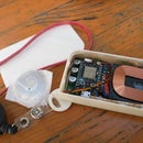
Step 4: Make It Mobile With a Power Bank and Connect a Speaker


At this point, the system should work laying on your desk. But you probably still power it from a laptop.
So, place all the electronics into the pumpkin. We decided to let the audio 3.5mm cable for the pumpkin leave the pumpkin at the back, so cut another hole. We also let the power cable come out, see the pics.
Congratulations! You now have a super scary and super funny halloween pumpkin!

Participated in the
Pumpkin Challenge


