

Introduction: Tinkerer's Baseplate - Arduino + Breadboard(s) + Periphery Holder


What is it good for?
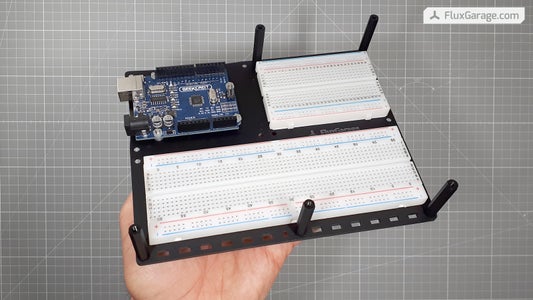
With this plate, you can put your Arduino Uno, a halfsize breadboard AND your project's periphery (e.g. knobs, potentiometers, sensors, leds, sockets, ...) onto a 3mm lasercut baseplate. If you need more space, there is also a larger version of the plate, that can hold an additional fullsize breadboard.
Compatible to the other FluxGarage elements:
Sure, both plates have compatible dimensions to carry the display shield front plate from my previous tutorial: Front plate for 16x2 LCD + Keypad Shield
You don't have access to a lasercutting machine?
If you don't have access to a lasercutting machine, use lasercutting services like ponoko (US/international) or formulor (EU/germany) to get the necessary arcylic-parts. You can find the regarding lasercut template files below.
Step 1: Gather Parts, Tools and Files


- 3mm lasercut acrylic glass elements
Download the template eps-file (below) and place your order at Ponoko (international users) or Formulor (german/european users). Choose one of the 3mm/0.118 inches acrylic P1-Plates in a color you like. I'd suggest to choose “Acrylic - Black (Matte 1-Side)” or “Acrylic – White”. If you have access to an own lasercutting-machine, just import the vector elements into your familiar software. - Arduino Uno (or similar)
- Halfsize Breadboard
(+ add a fullsize breadboard if you want to use the large tinkerplate) - 8X Countersunk screws M3 x 10mm
(to fix the arduino and the distance bolts, + add 2 more screws for the large tinkerplate) - 8X M3 plastic nuts
(to fix the arduino) - 4X distance bolts M3, Female-Female, 35mm height
(to fix the "toothbar bridges", + add two more distance bolts for the large tinkerplate) - 4X pan head screws M3 x 7mm
(to fix the "toothbar bridges" onto the distance bolts, + add two more screws for the large tinkerplate) - 6X self adhesive silicone pads
(to prevent your table from being scratched)

Step 2: Prepare Lasercut Plate

The most elegant way to prepare the underside of the tinkerplate is to cone-shape the holes with a proper drill, use countersunk screws and add self adhesive silicone pads.
Step 3: Add Arduino, Distance Bolts and Breadboard(s)


Fix Arduino
- Put four countersunk screws through the plate and fix them with plastic nuts (on the left where the Arduino is to be mounted)
- Put the Arduino on the screws and fix it with the plastic nuts. Sometimes it's not possible to screw all 4 nuts onto the screws due to a lack of space on the arduino. But three nuts should be enough.
Fix Distance Bolts and Breadboard's
- Attach the 4 distance bolts with the countersunk screws on the outer holes
- Take your breadboard(s), peel of the foil and stick them to the plate
Step 4: Make Use of the Toothbars


Now we're coming to the most interesting part of this solution. Whereas there are sold many plates that carry an arduino + breadboard, I haven't yet found any system that carries all the other elements that are typically used while tinkering, such as piezo speakers, sockets, switches, potentiometers and so on. By attaching those elements to a "toothbar", you can mount them in a very stable way on the plate's sides. Those parts won't get lost or fly around while worling on your project or putting your stuff back to the locker or drawer. Somehow this solution fills the gap between prototyping and boxing up your projects.
Please note!
The squareshaped holes on the plate are designed for 3mm toothbar-thickness. If you plan to use 2mm or 4mm thick materials, the whole system probably won't work without further adjustment of the template file!
How to attach periphery:
In most cases, it's enough to just drill a proper hole into one of the raw toothbars. The templates are prepared with 16mm, 7mm and 5mm holes. For more complex or very large sized holes it makes sense to prepare a lasercutting path in the template files before producing the plates. The examples in the images show how you can use a toothbar for...
... a power socket
... two cinch sockets
... a pushbutton + LED
... a 4-pin socket
... a potentiometer
... an Arduino sticker :)
How to fix the "toothbars":
To fix the "toothbars", just plug them into the squareshaped holes, lay the "toothbridge" on them and fix it with the pan head screws on the distance bolts. For the small "Tinkerplate", the template contains a top-cover that can also be used if you prefer a more boxed up appereance (see images in step 1 and 5). This makes most sense if you additionally use one of the display frontplates as well.
Step 5: Now Create Your Own Prototyping Economy


I personally have many of those plates and work with them every day. For example, I use one tinkerplate set for my "stepper motor + camera trigger controller". I like the fact that I have some kind of boxed up and stylish device that holds every project together and can be easily put into the drawer while still being an open system that can be extended and further developed. As already said, this system fills the gap between raw prototyping and developing a final enclosure.
If you like this approach, it's now time that you create your own prototyping environment based on this template and hopefull share it to the community!
Add a display with frontplate:
As mentioned above, I already published a template to build a frontplate for the Adafruit 16x2 LCD + keypad shield, that perfectly fits to this plate.
More display frontplates coming soon:
I'll soon publish templates for compatible frontplates that carry oled displays and rotary encoders while having a "notch" that allows full access to the underlying arduino pins (look at above's images for a preview).


