

Introduction: Tiny ESP8266 Dash-Button (Re-Configurable)


![Neon Stick (USB Neon Inverter) [And Flash Drive...]](https://content.instructables.com/F8K/ZPG9/J3AFAZMV/F8KZPG9J3AFAZMV.jpg?auto=webp&crop=1%3A1&frame=1&width=130)
This is a tiny ESP8266 based dash-button. It stays in deep sleep, once you press the button it performs a GET request to the specified URL and if configured also passes the supply voltage as a variable. The best part is that by simply bridging two pins you can make it enter configuration mode. Allowing you to change all the settings without reprogramming.
For following along this instructable I am assuming you know some things, like; how to solder, how to follow a schematic and how to upload a program and SPIFFS data to an ESP.
Step 1: Materials and Tools Needed


For this project you will need:
- An ESP-01 (Obviously)
- A 50mAh or similar Li-Po Battery
- 2x1 female pin header
- A 3.3V LDO (Highly recommend the HT-7333A, It has an excellent standby current of 4uA and 170mV dropout)
- A tiny push button
- Some thin wire (Wire wrapping wire works great)
You will also need:
- An ESP programming board
- A soldering iron / solder / flux
- A desoldering pump
- Tweezers and/or wire strippers
- Sandpaper
- Superglue
Step 2: Programming

This project is fully open source, if you want to modify the code it's on my GitHub. But there is no need to. This button can be reconfigured without reprogramming.
You can download the pre-compiled code here.
Just plug in your ESP programmer and your ESP8266(Remember to connect GPIO_02 to GND to enter programming mode) and upload the .bin file and the SPIFFS data.
It's very important to upload the SPIFFS data folder, without it the code will not boot. And after removing the pin headers having to go back to reprogram will be very tedious.
Step 3: How the Code Works (If You're Interested, Otherwise Just Skip)


When the ESP boots up, it reads and parses the 'config.jsn' file from the SPIFFS file system using the ArduinoJSON library. This loads up all the configurable settings into variables.
Then it checks to see if GPIO_03[RX] is connected to ground if it is it will enter configuration mode.
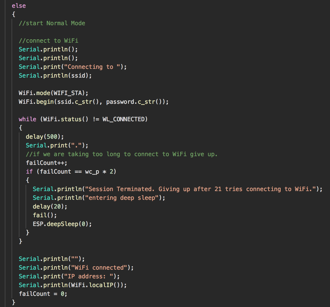
If it is not it will attempt to connect to WiFi and then the server. It completes a GET request and enters deep sleep to conserve power.
In configuration mode, you can set all the settings. (more on this on step 13)
Since saving power is essential here, if anything takes too long or if connecting to wifi/server fails, it will simply blink five times fast and then a long blink to indicate an error and return to deep sleep.
If it all goes right, it will do a short blink then a long blink. To show it succeed. Then enter deep sleep.
Still curious? have a look on my GitHub.
Step 4: Schematic

This should help you build it, during the next few steps.
Step 5: Desolder the Pin Header

First, be 100% sure that you programmed the ESP8266 correctly and 100% sure you uploaded the SPIFFS data.
Then the first step is to desolder the 2x4 pin header, this will let us make our button smaller. But it also means you can't reprogram without resoldering it. Make sure the program and SPIFFS are flashed.
You will still be able to reconfigure the settings.
This is a lot easier with a pointy soldering iron tip and a desoldering pump. My strategy is to first bridge all the eight pins with solder, then heat all of them at once and yank the header out with some tweezers. Then after removing the excess solder, I poke the holes from the top with the iron and suck the solder out with my pump through the bottom.
Step 6: Solder the Switch

Next, you will want to solder your push switch between GND and RST. In my case the button pins were just a bit too thick, so I had to cut them a bit thinner with some snips. Make sure the button sits flush with the board, otherwise it might break over time with the stress of being pushed.
Step 7: Connect CH_PD to VCC

To allow the ESP to run the code, don't forget to connect CH_PD to VCC.
Step 8: Remove the Power LED


The button needs to consume as little power as possible. And since it is always on, the power led would always be consuming ~4mA. This would reduce the battery life to twelve hours. So desolder it or snap it off.
Step 9: Solder Configuration Switch

To enter configuration mode, GPIO_03[RX] needs to be connected to GND. To make it easy to do so I soldered a little lever that can be pushed to the side to make the connection.
Step 10: Add the Power Supply, Regulator and Connector


This is the longest part of the build. You will need to solder the battery, voltage regulator and the charging connector according to the schematic.
To make it all fit within the tiny space under the ESP-01 I had to sand down the voltage regulator's TO92 package. Make sure to plan your layout before soldering, it will be very tight but should be still do-able.
If your battery is too big, you might choose to omit the voltage regulator. This will work but will risk damaging the ESP8266. It is only rated to go up to a maximum of 3.6V, but a fully charged LiPo outputs 4.2V. Proceed at your own risk.
Step 11: Superglue It Toghether


The last step to keep everything in place is to superglue everything in place.
Step 12: Charging

To charge your button you will need some sort of LiPo charger, I simply use a generic USB Li-Po charger board connected to the button via the charging connector. Be careful not to switch the polarity around.
Step 13: Configure

You are almost ready to use your button for the first time.
To enter configuration mode you need to connect GPIO_03[RX] to GND, this will be easier if you soldered a lever like in step 9. Then by pressing the button to reset the ESP, it should enter configuration mode. You can now disconnect the lever.
Then you can simply:
- Connect to 'ESP_Button' WiFi Access Point, with the password 'wifibutton'
- Visit http://192.168.4.1 to open the configuration page.
- After setting your values, click on the 'Save' button then the 'Restart'
- Your button will restart, perform the request and enter deep sleep.
Make sure to only type the hostname in the host field, no http:// or https:// and separate the rest of the URL in the URI fields.
Step 14: Try It Out
You should be all good to go, pressing the button will make your GET request.
The video above is my button connecting to my website and IFTTT, posting a custom generated tweet.
Setting up the GET request is out of the scope of this instructable, but you should easily be able to connect this to IFTTT or any other service. If you are willing to write some custom PHP code and host it on your own website like I did you might even be able to monitor the battery.
If you have any issues or need help troubleshooting please leave a comment down below.
Anyone is welcome to give ideas on how to improve this, like maybe a case? xD
Leave a comment if you are a Doctor Who fan.
Cheers!
Step 15: Update: 3D Printed Case


After some time using the dash button i've decided to make a case for it. STL and Fusion 360 files attached.


Participated in the
Epilog Challenge 9


