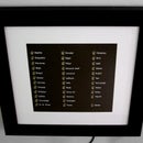
Introduction: Vintage Toothbrush Timer
Step 1: Circuit Design
The circuit is designed around a wight sensor. I got one from a used digital scales. It is a pretty basic device: there are four wires: one is input current, one is ground and voltage difference between the other two wires is determined by a weight of an object on the scales. The difference, however, is really small, so one needs to use an amplifier to be able to tell that the weight has changed.
Here are components that I chose:
ATMega328p with 16Mhz crystal – I chose this micro-controller because it is extremely easy to use. There is also a good community support, as ATMega328p is used in one of Arduinos.
Ina12P amplifier – this device is created specifically for amplification of sensors' signals. It is not hard to use it. The only thing that I found tricky is figuring out the right resistance value for amplification gain.
TPS2020 switch – this is a great switch with a very low standby current ( <10 μA). I use it to control power of the servo that chimes.
MAX1555 charger – this device controls charging of device's lithium-ion battery.
2N3904 transistors – used to control lamps' power.
Lamps – I chose incandescent lamps out of esthetic reasons. Since I wanted to give the project a "vintage" look LED lamps did not quite fit the design. Although these lamps consume more power the feeling they evoke is quite worth it.
This device is able to work 3 weeks on a single charge.
Full schematic could be found on Github.
Step 2: Printing the Circuit
I used photo-resistive method to etch the circuit.
Step 3: Programming
There program is pretty strait-forward. Source code could be found on GitHub.
Step 4: Enclosure Design
Step 5: Putting Everything Together
Once the enclosure was ready I have put the circuit inside and connected all wires. Photographs attached to this step show how it all fits inside.
I would be happy to answer any questions and hear any comments about this project.
I also hope this device will inspire you to create some creasy contraptions of your own!


