

Introduction: Treadmill Motor for Taig Lathe


When I bought my Taig lathe two years ago, I went through my junk pile and came up with a ¾hp motor. The spindle did not quite fit the Taig factory supplied pulley and I had to make it fit, by filing it down with the motor running, and shiming the then undersized result. The pulley belt is tensioned by moving and locking the motor closer or further away from the lathe. Every time I moved the belt position on the pulleys to change speeds, I had to move the Taig spindle head and re-tension the belt.
This motor has served me reasonably well over these two years. However I find it frustrating to be confined to only certain speed settings, to make adjustments to the belt tension and the position of the lathe spindle head all the time, and not be able to fine tune the optimum speed while on the job.
I therefore decided to change to a variable speed motor. The simplest way to do this is to run an DC motor off an electronic speed controller.
I managed to get a used treadmill motor off the second-hand market, and to purchase a Chinese variable speed controller both at a very reasonable cost. The treadmill motor is rated at 110VDC, 4hp input power, 4200rpm max. The controller is rated at 0-90VDC PWM, 400W maximum output power. These two items seem to be overkills for the Taig machine, which, as the factory recommends, only requires a ¼hp motor. The treadmill motor is bulky and heavy. Also, the controller output of 90VDC max seems not to deliver the full power of the motor at 110VDC. Well, I have to make do with what I can get.
All these however do not bother me at all. Firstly, running a 110V motor from 90V reduces its power by a third, but this still gives me ample power with plenty of margin for the modest requirement of the Taig. It also means that the motor will be drawing a smaller current and be running cold, giving it a better service life. Secondly, I can use its weight to tension the belt without the help of tensioners, so that it actually becomes an advantage. The motor is installed at a lower elevation using a longer belt, keeping clear of the lathe bed so its bulk does not really matter. In the process, I had to rebuild the lathe table, fabricate two new pulleys, and purchase a new belt.
Step 1: Installation: the New Table


The lathe is fixed to the top of a small wooden table with four #10-24 long bolts. When I first installed the lathe two years ago, I found that I had to prop up the lathe bed to allow more hand room for turning the axles on the cross slide. I did this by inserting a peice of ¾" wooden board between the table and the lathe bed. This proves to be inadequate as it still gives me little room to brush out chips from underneath the lathe bed.
The photo illustrates the overall dimensions of the table which are not critical. I chose them to make use of some scrap boards I had on hand.
The treadmill motor is mounted onto another piece of thick wooden board. This board is attached to the backside of the lathe table with two heavy duty door hinges. This allows the motor to be raised and lowered by swiveling around them.
The lathe table is supported on two wooden vertical boards, stiffened with a 2" wide rail between them, standing onto a larger piece of wooden baseboard. All wooden pieces are put together with #10 wooden screws. All wooden boards are made from either ¾" thick melanin laminated fibreboard, or plywood board. The melanin laminated board is used for the table top, to save me the trouble of painting and protecting it from chips and lubricant when the lathe is used. Rubber padding feet are placed underneath the bottom board to minimize vibration being transmitted to the wooden frame onto which the lathe table is placed and attached.
Step 2: Installation: New Hardware


In this new installation, I made four stand-off pillars, 1¼" tall, with a 5/16" length of #10-24 thread on top, and a ¾" length of 3/8-18 thread at the bottom. These pillars are attached to the lathe bed and the table top, using self locking nuts for the upper threads, and t-nuts for the bottom threads. There is no magic in choosing the height of 1¼" but any shorter will not give the clearance desired.
Power from the motor is transmitted to the lathe with belt and pulley. I replaced the thin v-belt which came with the Taig lathe with a new 10mm XL-240 timing belt, which provides excellent strength without being unwieldy. In order to use this new belt, I needed suitably sized pulleys. Inexpensive belts and XL pulleys can easily be purchased from on-line stores. Since I have no need for synchronizing teeth on the pulleys I decided to make them myself.
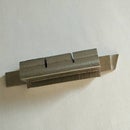
Using two cup-cake sized ingots which I have molten from scrap aluminium, I turned them into two 50mm diameter pulleys with 11mm wide tracks for the belt. They are centre bored 16mm to fit onto both the motor and the lathe spindles. Cross holes are drilled on the rims, tapped M5 to accept M5 grub screws for fixing onto the spindles. In making these pulleys, I took care to make sure that they run true on the spindles. Any wobble will, at certain speeds, cause resonant vibrations which degrade the performance of the lathe as well as produce undue wear on the spindle bearings and the connecting belt.
Step 3: Completion and Test


Having fabricated the table and the pulleys, I disassembled the original setup. I installed the lathe onto the new table with the four steel stand-off pillars and affixed the motor onto the motor mounting board. The clearance provided allows me to clean out chips very easily, and a lot of room to wrap my fingers around the cross slide dial handles.
I installed the electronic speed controller onto one of the side legs of the lathe table, connected it to mains as well as to the motor. I put the new pulleys onto the motor spindle and the lathe spindle and fixed them with the grub screws provided. I then raised the motor by swiveling it upwards on its hinges, and put the new 10mm belt onto the pulley tracks. Once the motor is lowered, its weight provides the tension on the belt. The lathe is now ready to be tested.
Switching on the power, I run the lathe from about 100rpm to 3000rpm, changing speed smoothly and continuously at any time. The upper speed seems to be somewhat limiting. However, I think that for most purposes it is good enough. If not, I can always make a new pulley to gear it up. I then test turn and cut off a few pieces of steel rod with various diameters. Choosing the optimum speed is now easy and the operation is smooth. The motor, as expected, runs cool and provides high torque even at low speed. The electronic controller does not heat up at all.
When the lathe is not in use, I raise the motor and prop it up with a wooden wedge. This removes tension on the belt and gives it a longer service life. For now, I have to read the rpm with an optical tachometer. In time, I intend to make a built-in sensor and display.
I am happy that I have made this modification which allows me to use the lathe easily with more flexibility.
Postcript:
I have since fabricated a tachometer using the 1602 LCD display driven by a 16F628A pic connected to a A3144 Hall Effect sensor. Two magnets are attached to the inside of the motor fan. Although you can buy a cheap rpm speed display in a e-store, I decided that it was more fun to make one. See the embedded video clip above.


