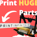
Introduction: Turn Your 3D Printer Into a Factory: Automatically Remove Parts
3D Printing is amazing! The technology allows anyone to make incredibly complex things.
However, 3D printers have one annoying flaw. After a 3D printer is finished printing a part, that print job is stuck to the print bed. A person must physically go to the printer and manually scrape off the part. This constraint significantly limits the application of 3D printers. It prevents 3D printing from being used for mass production purposes.
In this Instructable, we will automate 3D printers. Our modified 3D printer will be able to print a constant stream of jobs. A person will be able to send a queue of print jobs to our 3D printer, and the printer will spit out the parts one at a time.
I have been tinkering with this idea for some time and built multiple automated 3D printers. I am basing this Instructable off an earlier design that I felt was easier for others to replicate. I have also posted videos of later designs above.
Step 1: How This Works
Our 3D printer is going to eject print jobs with a conveyor belt. The printer will print directly on the conveyor belt module. Because the conveyor belt is relatively large and bulky, I recommend applying this hack to a Delta 3D Printer. Since a Delta 3D Printer has a stationary heat bed, it will be much easier to add in the conveyor belt.
Step 2: Parts List
I designed this mechanism to work with a Delta 3D Printer that I could tinker with. The design can easily be tinkered to work with other 3D printers.
To add a conveyor belt to your 3D printer, I would recommend following this Instructable as a general guide instead of following it to the letter.
Parts List
- 1/4 x 16 x 8 inch Aluminum Plate
- 3/8 x 32 inch Aluminum Round Stock
- 1/2 x 10 inch Aluminum Square Stock
- 8-32 and 6-32 Bolts
- 8 Ball Bearings(3/8 Bore, 7/8 O.D.)
- Kapton Tape
- 12 V High Torque Motor(I salvaged one from a broken robotic vacuum)
- 12 V H-Bridge Motor Driver(I'm using a standard L298n)
- Limit Switch
- 20 Gauge Heat Shrink
- 20 Gauge Wire
- .002 x 6 x 50 in Stainless Steel Shim
Required Tools
- Aviation Snips
- Drill Press
- Drill and Hole Saw Set
- Soldering Iron
Step 3: The 3D Printer
First, we need to find an old 3D printer that we can retrofit with a coveyor belt.
I decided to build a conveyor belt for a delta 3D printer. Since a delta's build plate does not move, it is easy to integrate components with the bed.
I searched on Amazon and found a relatively cheap second hand Delta 3D Printer kit.
After putting the printer together and running a few test prints, I began designing the conveyor belt ejection module.
Step 4: Print Out Parts
Print out all of the attached files.
I recommend printing all of the parts at the beginning of this project, since we will be hacking the 3D printer later on.
The files include:
-Bearing Housings
-Drums
-Mounts
-Tensioners
-Shear
Attachments
Step 5: Press Bearings Into Bearing Holders
Press a ball bearing into each holder.
I recommend using a vice or mallet for this process.
Also, make sure to order the correct size bearing. My bearings were slightly too small for the bearing holders. I ended up wrapping the bearings with tape to increase the O. D.
Step 6: Mount Drum on Axle
Cut the aluminum rod into 8 inch segments.
Mount the 3D printed drum on one of these axles.
To insert the axle in the drum, use a mallet and slowly hammer the axle until it is centered in the drum.
I wanted my drum to be bolted to the axle. So I machined 8-32 tapped holes in the axle and then bolted the drum in place.
To be honest, bolting the axle in place is a bit overkill.
Just a friction fit should be more than enough to keep the drum in place on the axle.
Step 7: Add Traction to Drum
I wanted the drum to have a one inch radius. But at the time I was low on filament, so I made the drum at a smaller radius.
I then wrapped the drum with masking tape to increase the O. D. until it was two inches.
Once your drum is the appropriate size, wrap it with electrical tape. The electrical tape will ensure the drum has appropriate traction while driving the belt.
Step 8: Machine Mounting Holes in Plate
All components of the conveyor belt will be directly/indirectly mounted to the aluminum plate.
Drill and tap the following holes on the plate as shown in the technical drawing. These holes will later be used for mounts.
Make a large cutout near the top of the plate. This cutout will be used for cable management. I made the cutout with a hole saw and file to smoothen the cut.
Attachments
Step 9: Mount Rollers on Plate
Insert the aluminum axles into each of the appropriate bearing blocks.
Then, bolt both of the end bearing blocks to the metal plate. Don't mount the middle roller just yet. We'll attach it later on.
Step 10: Mount Heatbed on Plate
Bolt the heatbed to the correct holes on the aluminum plate.
Step 11: Mount Belt
Wrap the metal shim around both of the rollers. Cut the shim to an appropriate length and then attach both ends with Kapton tape.
We want the belt to have high tension. Insert the middle roller to stretch the belt out appropriately. When mounting the middle roller, I placed a spring between the aluminum plate and bearing block.
Step 12: Mount Belt Tensioners
When printing, we want to ensure that the belt is flat against the heat bed.
To ensure the belt is flat, bolt the four tensioner pieces on the heat bed.
Step 13: Mount Conveyor Belt on 3D Printer Pt. 1
The conveyor belt will be attached to the 3D printer through four 3D printed clips.
Position the four 3D printed clips appropriately on the printer frame and bolt them in place.
Place the conveyor belt on top of the mounts and then bolt them in place as well.
Step 14: Mount Front Stands
Cut the square stock into 5 inch components
Drill and tap an 8-32 hole in each bar.
Bolt both bars at the front of the conveyor belt.
Step 15: Motorize Axle
To motorize the front roller, I used a specific old motor that I had lying around.
I doubt most readers have access to the same motor. But the process should be similar for any motor.
To mount the motor, I drilled an 8-32 hole in axle. I designed and printed an adapter that connects the motor to the axle. I then bolted all three components together.
Afterwards, I drilled and tapped holes in the left stand. I then made an adapter that secures the motor body to the stand.
Step 16: Test Belt and Ejection!
At this point, we want to make sure that the motor can properly drive the belt.
Connect the motor directly to the PSU or place a small switch in between if you have one handy.
Activate the motor and check if the belt runs fine. The belt should not skip or stall. Ensure the belt remains relatively inline as well while running.
Once you ensure the motor drives the belt correctly, try running a test print. Adjust the z-height so that the printer zeroes at the conveyor belt. Then run a print job on the belt. Once the print job is finished, eject the print by turning on the motor.
During my first tests, I noticed that some prints would still stick partially to the belt while going over the conveyor belt.
Step 17: Add Shear
To ensure all of the parts eject successfully, position the 3D printed shear at the front of the conveyor belt.
Step 18: Position Limit Switch
Solder wire to the limit switch.
Then bolt the limit switch at the top of one towers.
Ensure that the limit switch is triggered whenever the extruder is in the home position.
Step 19: Wire Motor to Motor Controller and Arduino
Wire the motor, limit switch, and Arduino as seen in the wiring diagram.
Afterwards, upload the Arduino code to the Arduino.
Attachments
Step 20: Dry Test!
Push the limit switch. The conveyor belt should drive forwards for a long period. Ensure this length of time is long enough to eject a print job.
Step 21: Run a Test Print
Run a print job on your 3D printer.
Ensure that the G-Code file has this command at the bottom of the file.
G28
This will home the 3D printer at the end of the print job.
When the 3D printer homes, it will trigger the limit switch which will command the conveyor belt to roll forwards.
Step 22: Mass Produce Parts
To print multiple parts, copy and paste all of the G-Code into one file. Then run this file on your 3D printer.
I found this process quite tedious, so I made a simple Node.js application that stitches the files together.
Step 23: Future
For the next iteration of this 3D printer, I would like to integrate the conveyor belt into the 3D printer. I would like the conveyor belt to be one of the axis of the printer. It would be far more efficient for the conveyor belt to provide all of the y-axis movement.
In future design iteration, I would like to simplify the mechanism in this way.

Participated in the
Make it Move Contest


