

Introduction: Voltage Amplifier

A voltage amplifier in simplest form is any circuit that puts out a higher voltage than the input voltage. When you are forced to work with a set amount of voltage, these amplifiers are commonly used to increase the voltage and thus the amount of power coming out of a circuit. This is useful for reading and adapting small signals such as boosting an audio signal before sending it on its way to speakers. The voltage amplifier is a form of the common emitter amplifier, which relies on the transistor; the amplification of voltage is dependent on the ratio of resistors on the collector and emitter of this transistor.
The following materials are for an amplifier with a gain of 10. If you want to increase or decrease this factor, refer to step 2.
Materials
To build this circuit, you will need the materials listed below. Names of specific instruments used in this particular circuit are included in parentheses.
- function generator (BK Precision 4011A 5MHz Function Generator)
- breadboard (Global Specialties Proto-Board PB-503)
- DC power supply (15V, included in our breadboard)
- transistor (Q1 2N3904)
- capacitor - 100nF
- resistors - 56 kOhm, 5.6 kOhm, 6.8 kOhm, 680 Ohm
If you are using this circuit for practical purposes, you can use any DC power supply you desire; keep in mind that your output voltage can not be larger than the voltage provided by this DC power supply. Therefore I would recommend power supplies in the range of 9 to 15V DC. The sine input from the function generator is simply the input that you wish to be amplified.
Additionally, you will likely want something to read or use the output voltage produced by this circuit, depending on your reasons for wanting to build a voltage amplifier. If you are simply looking to investigate the circuit, an oscilloscope can be used to read the output voltage.
Again, this circuit has an voltage gain of 10. For different values of gain, different resistors will be needed (see step 2).
Step 1: Building the Circuit
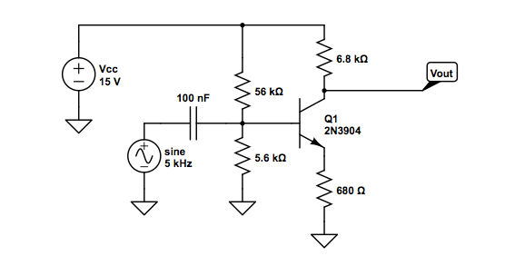
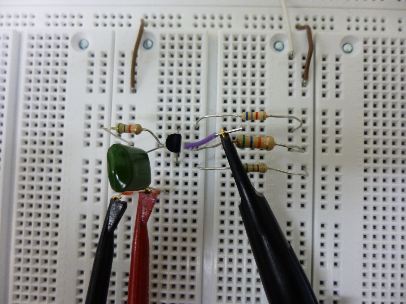

The first image is the schematic of the circuit; the bottom right is the breadboard view; and the bottom left is our final product.
Let's talk a little about the circuit before you start building it. If we completely ignore the sine input, we can see that there will still be a complete circuit and therefore a voltage at the output. Based on the ratios of the resistors used here, this voltage (called the quiescent voltage) calculates out to be about half of the input voltage. With the voltage already at such a large quantity, it makes sense that the addition of this sine input voltage, even if small, will lead to a much larger output voltage. Hence the amplifier!
A note about the capacitor:
The first two resistors are what set the DC voltage of the base. The capacitor acts to filter out the DC current from the function generator, leaving only a sine wave so as to keep the AC voltage from interfering with the DC voltages.
So now lets begin building the thing! The most efficient and wire free way to go about doing this would be to leave all connectors until the end. Starting with the transistor and the resistors, the circuit looks easy enough so I wont try to guide you through it. Once this base is done, the function generator (bottom left in red and black) can be connected and then output (which is shown here as the purple wire connected to a probe).
If you are going to look at the results on an oscilloscope, I recommend using the TTL output of the function generator as the external trigger for the scope. If you are actually going to hook it up to sometime, I still stand for checking your work first-- you never know what can go wrong!
Step 2: Calculating the Gain


An essential part of building a voltage amplifier is knowing how much your voltage will be amplified by! You can determine the gain of your voltage amplifier by choosing appropriate resistors (top image), and an oscilloscope will tell you how much your voltage is actually being amplified (bottom image).
The gain of this voltage amplifier is simply the ratio of the transistor’s collector voltage (Vout) to its base voltage (Vin). This ratio is equivalent to the negative of the ratio of the collector and emitter resistors RC and RE such that Gain = Vout / Vin = - RC / RE . In our example circuit (see top image), the ratio of these two resistances was 6800 Ohms (in red) / 680 Ohms (in blue) = 10, so our voltage amplifier had a gain of -10; thus, the output signal is the product of inverting the input signal and increasing its amplitude by a factor of 10.
To build voltage amplifiers with other gains, choose resistors RC and RE such that their ratio is equal to the desired gain.
The negative factor in the gain indicates that the input and output signals will be completely out of phase from one another. Another way of thinking about the inverted signs of the output signal is to imagine that the circuit shifted the signal horizontally by a phase shift of pi radians, or 180 degrees. This phase shift/sign inversion can be confirmed by viewing the input and output voltages on an oscilloscope display. In the oscilloscope display image above, Channel 1 and Channel 2 read the output and input signals, respectively. Note that the two signals are displayed with a difference of scale, so that the Channel 1 output signal is amplified, though it looks to be roughly the same size as the Channel 2 input signal.
Step 3: Potential Problems

One of the most common problems surrounding transistors is the occurrence of clipping. In this specific case, clipping will occur when the voltage at the base is higher than that at the collector; this will cause some of the the current to flow from the base to the collector as opposed to the desired base to ground.
The current will begin to clip at very low gains--those around 1 or so. For a more detailed description on how this was calculated, either try it yourself or see below*. Luckily, I do not think that this will be too large of a problem for anyone because why bother with a voltage amplifier that doesn't work to amplify the voltage?
Other problems are usually caused by unfortunate mistakes in wiring. Also, it is important to note that while your resistor ratio may signal a desired gain of some amount, circuits are hardly ever perfect, so there will be some variation. For high gain, the actual gain seen will be slightly smaller than the ratio, whereas for lower gains, the actual seen will be slightly larger than the ratio of resistors.
*More Detailed Explanation:
Looking at the 5.6k and 56k resistors as forming a voltage divider, we can calculate that the voltage at the base is going to be 1.36 volts on average. Clipping will therefore occur when the collector is 0.6 volts smaller than this (accounting for the voltage drop over a diode). This turns out to be about 0.8 volts. Since the output voltage is just the gain, the circuit will begin to clip at a small gains in the vicinity of 0.8 or less.
Step 4: Applications and Final Comments

The common emitter amplifier can be a very useful circuit not only because it inverts and amplifies a voltage signal but also because the capacitor at its input allows it to ignore the constant component of an input signal (the DC offset) and pick up faint, low-frequency signals (the AC component of the input).
Its applications include use in speakers to amplify audio signals and in radios to amplify faint radio signals picked up by an antenna.
Good luck, and enjoy your voltage amplifier! Happy building!


