

Introduction: WIFI Plant Monitoring System Based on Arduino MEGA and ESP8266


Today we are going to show you our first experiment on the Internet of Things. For this purpose, we decided to use an Arduino MEGA instead of an Arduino UNO. That's because Arduino MEGA has more than one serial port and this fact allows us to use the ESP8266 and the serial monitor at the same time.
As written in the title, we'll see how to monitor some of the most important plant growth factors*. These parameters are:
- Ambient temperature and humidity
- Soil moisture and temperature
- Illuminance
Monitoring this parameters occurs via Internet thanks to the famous and cheap ESP8266 v01 wifi module.
Techrm's channel is available here. If you are lucky, you'll see it working.
As usual, let's list what we need to follow the tutorial:
- Arduino MEGA 2560
- USB cable
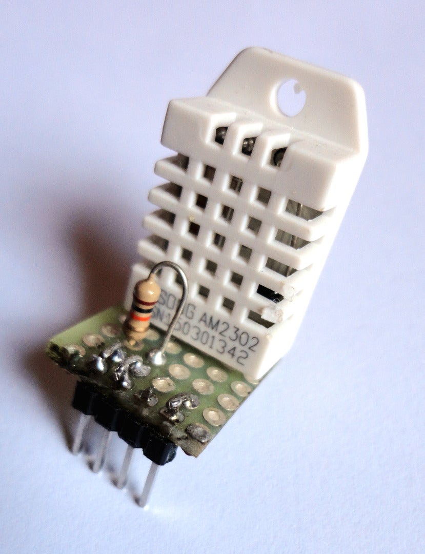
- DHT22 (more info about this sensor)
- ESP8266 v01
- Bi-directional logic level translator (we use our own by TechRM)
- LD-33V voltage regulator (3,3V-1A)
- Waterproof thermistor
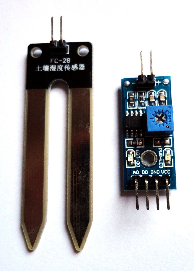
- YL-69 Analogue soil moisture sensor
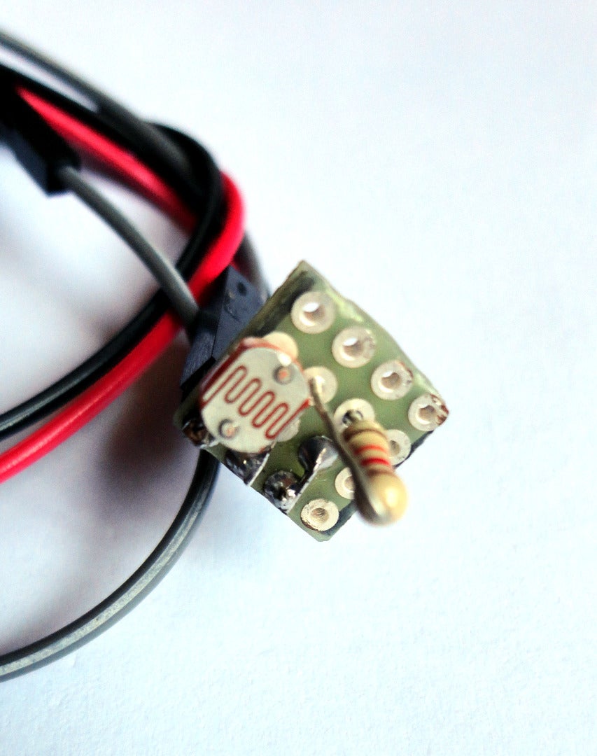
- Photoresistor
- Set of Dupont cables
- Breadboard MB-102
- Number 3 10k Ohm Resistors
NOTE: The ESP8266 wifi module works on 3.3V power supply but the Arduino serial ports work on 5V. That's why using a logic level translator between the ESP8266 and the wifi module is required. We have used our own logical level translator which has been very efficient on testing but you can use another one, for example: SparkFun Logic Level Converter - Bi-Directional
We built a limited number of them and anyone interested on purchasing our devices can find them on Tindie. We'll be thankful for feedback.
Another essential thing is the voltage regulator. Since the ESP8266 requires more than the 35mA supplied by the Arduino 3.3V source, you have to connect the 5V to the voltage regulator and take advantage of the larger amount of Ampere supplied by this power source.
*Even if we are going to explain how to monitor those parameters, following our explanation you'll be able to change sensors and monitor whatever you want.
Step 1: How to Properly Connect the ESP8266


The logic level translator
As previously mentioned, a logic level translator is needed in order to make the ESP8266 work. That's because the Arduino digital signals have values of 0V and 5V to represent logic 0 and 1 respectively, but the ESP8266 uses 0V and 3.3V. So, not using a logical level translator could damage you WIFI module. Vice versa, the two logic 0V and 3.3V from the ESP8266 won't damage anything but could be misinterpreted by Arduino, especially when communications are fast and/or in presence of noise.
The voltage regulator
ESP8266 modules have to be supplied with a 3.3V but their current absorption could reach 300mA. Since the current from the 3.3V Arduino supply can only reach 35mA, we have to use a 5V supply transformed to a 3.3V by using a voltage regulator. So, connecting a WIFI module to the 3.3V Arduino supply directly won't make it work at all.
Once explained the importance of these two devices, we can connect everything following the Fritzing scheme attached above.
Step 2: Sending Data to Thingspeak

In this step we'll try to explain you how the code works. The code is quite complex because of the presence of AT commands,required by ESP8266. So, this analysis doesn't claim on being exhaustive but it will only teach what you have to change in order to send data to Thingspeak. Look at this page for more info about AT commands.
Before going on, watch the video appended in this step for more info about Thingspeak basic settings and then set up DHCP on your router.
In the first part, we define the constants needed for the rest of the sketch.
#define esp8266 Serial1   // use esp8266 to talk to esp8266
#define SSID "SSID_NAME"    // put here the name of your wifi network
#define PASS "ROUTER_PASSWORD"             // put here the password of your wifi network
#define IP "184.106.153.149" // thingspeak.com's IP

String GET = "GET /update?key=[THINGSPEAK_KEY]&";    // put here your thingspeak key
String GET1 = "field1=";

String valuetosend = "10";                           // for this first test we send a simple value
We call esp8266 the serial port #1 for convenience, then we define our SSID name, the router password if you use one and the ThingSpeak IP. We also have three string variables: the first two represent the command line sent to ThingSpeak which is composed of GET and GET1. Replace [THINGSPEAK_KEY] with your key, automatically generated by ThingSpeak once done a new channel. Watch the video appended in this step for more info about. GET1 store data for the chart 1. For every sensor you have to declare a String.
The string called valuetosend is only a random value we use for testing.
The first function we find going on analysing the sketch is called updateFunction:
void updateFunction(String valuetosend){
  String cmd = "AT+CIPSTART=\"TCP\",\"";
  cmd += IP;
  cmd += "\",80";
  esp8266.println(cmd);
  delay(2000);
  if(esp8266.find("Error")){
    Serial.print("Error1");
    return;
  }
  cmd = GET + GET1;
  cmd += valuetosend;
  cmd += "\r\n";
  Serial.print(cmd);
  esp8266.print("AT+CIPSEND=");
  esp8266.println(cmd.length());
  if(esp8266.find(">")){
    esp8266.print(cmd);
  }else{
    esp8266.println("AT+CIPCLOSE");
  }
}
This function begins a TCP connection in the 80 port towards ThingSpeak. If everything goes well, it sends the command line for updating the chart.
The command line has the following structure:
GET /update?key=[THINGSPEAK_KEY]&field1=10
Just after, there is the connectWiFi function:
boolean connectWiFi(){
  esp8266.println("AT+CWMODE=1");
  delay(2000);
  String cmd="AT+CWJAP=\"";
  cmd+=SSID;
  cmd+="\",\"";
  cmd+=PASS;
  cmd+="\"";
  esp8266.println(cmd);
  delay(5000);
  if(esp8266.find("OK")){
    Serial.println("OK");
    return true;
  }else{
    Serial.println("KO");
    return false;
  }
}
Basically, this function makes your ESP8266 join your wifi LAN by using the command AT+CWJAP. If it establishes a connection, it returns true otherwise false.
As usual, the setup function initializes variables, pin modes and so on.
void setup()
{
  Serial.begin(9600);
  esp8266.begin(115200);
//  sensors.begin();
  esp8266.println("AT");
  delay(5000);
  if(esp8266.find("OK")){
    connectWiFi();
  }
}
It initializes the two serial communications, prints "AT" and then tries to connect the ESP8266 to your wifi LAN printing "OK" if this attempt goes well. Keep in mind that you have to initialize here all the digital and/or analogues pins used by those sensors you need.
The loop function simply calls back the updateFunction (seen above) and waits 5 seconds before coming back and starting again. Change the delay time according to your needs.
void loop(){
  updateFunction(valuetosend);
  delay(5000);
}
Attachments

Step 3: Adding a Sensor to the Basic Sketch
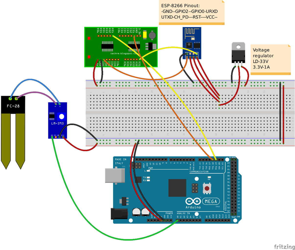
Once understood how the basic code works, we can add a sensor and make it send data to Thingspeak. We chose to add a soil moisture sensor called YL-69. Connect it as shown in the Fritzing scheme attached in this step and then stick it in soil.
We are not going to see how to add every single sensor used in this project because basically it's just a matter of repeating the procedure shown in this step*.
Constant and variables required
The first thing we're going to do is defining a constant for the pin used by the soil moisture sensor. Then, we declare a string variable needed to store its data.
#define soilMoisturePIN 0 // soil moisture sensor connected to Analog Pin 0
String soilMoist = "";    // sends soil moisture values
The soilMoisture ()
Now we have to add a new function which basically transforms analogue values of the soil moisture sensor into a percentage and then converts them into strings. As you should know from the previous step, Thinkspeak only accepts strings, so this conversion is strictly required.
String soilMoisture (){

    float moisture;
    char moisture_c[6];
    //calculates the percentage of soil moisture
    moisture = analogRead(soilMoisturePIN);
    moisture = 100*(1-(moisture)/1023);

    dtostrf(moisture, 0, 1, moisture_c); //converts floats to strings

    return (String) moisture_c;
}
How does this conversion take place? It's pretty simple. Declare a 6 elements char array and then convert floats by using the function dtostrf.
dtostrf has the following syntax:
dtostrf (float_to_convert, minimum_length_of_the_string, decimal_significant_digits, the_string_array_previously_made);
Of course, your functions will have to return a string.
NOTE: soil moisture is 0% when the sensor indicates 1023, and 100% when indicates 0, yours may be different!
Sending data to Thingspeak
The function upadateValues is essentially like the one seen in the previous step. In fact, we only changed the value to send from valuetosend to moisture_c.
void upadateValues(String moisture_c){
  String cmd = "AT+CIPSTART=\"TCP\",\"";
  cmd += IP;
  cmd += "\",80";
  esp8266.println(cmd);
  delay(2000);
  if(esp8266.find("Error")){
    Serial.print("Error1");
    return;
  }
  cmd = GET + GET1;
  cmd += moisture_c;
  cmd += "\r\n";
  Serial.print(cmd);
  esp8266.print("AT+CIPSEND=");
  esp8266.println(cmd.length());
  if(esp8266.find(">")){
    esp8266.print(cmd);
  }else{
    esp8266.println("AT+CIPCLOSE");
  }
}
connectWiFi doesn't change at all.
Setup and Loop functions
These two functions only differ a little bit from the ones seen before.
Into the setup we find an additional line needed to initialized the soil moisture sensor.
pinMode(soilMoisturePIN, INPUT);
Into the loop we simply call back soilMoisture and upadateValues.The first function detects and the calculates moisture content, the second one sends it to ThingSpeak.
void loop(){
  soilMoist = soilMoisture();
  upadateValues(soilMoist);
  delay(5000);
}
*NOTE: our final sketch contains a function named getValue which is required to split strings from DHT22. This operations is called Tokenization. Check the this page for more info about.
Step 4: Observations and Tests


Before talking about our impressions on ESP8266 module, let's spend few words about thermistor and photoresistor.
In order to set up formulas correctly, both photoresistor and thermistor need their respective "nominal resistance" values. These values are usually provided by manufacturers and can be found on datasheets. Unfortunately, we couldn't find any datasheet for our two sensors and had to estimate the nominal resistance values using an empirical approach.
For the thermistor, you can compare temperatures detected with a normal thermometer (or with a sensor like DHT22) and the ones detected using the thermistor. Then, you have to change the value float thermr (in the thermistor function) according to the exact temperature. You may have to repeat this procedure several times to achieve a good result.
It's much more complex to define the exact nominal resistance value for a photoresistor. In fact, we didn't have a Lux meter and had to adjust the formula* till the sensor has been detecting a value around 50-100Lux into a bedroom.
This is an example of a photoresistor datasheet.
Our opinion about ESP8266 v01 modules
We have been testing this system for a couple of weeks and we can say that ESP8266 v01 modules are a little bit disappointed for the reasons listed below:
1) needs a large amount of electricity and adding more sensors means to increase the power needed
2) often disconnects from WLAN without a specific reason (updating the firmware may solve this problem).
3) can't work properly if there are walls between router and module
4) looks like it misses a lot of packets (tested using wireshark)
*double luxValue = pow((30000/photoResistance), 1/a);
NOTE: we are till testing this system in order to improve it so, if you notice a problem and/or have any suggetion, please tell us!

Participated in the
Home Automation


