

Introduction: Web Based Remote Engine Preheater


This Instructable will detail a very specific web based control and monitoring method which can be generalized for many other uses.
One of my hobbies is flying small aircraft in Ohio. Ohio does get very cold in the winter and trying to start a small aircraft engine in the middle of winter, without it being pre-warmed, can be next to impossible.
This Instructable details how I made a web based preheater for my small airplane which I could activate remotely from any PC or smartphone. From the system that I will detail, I could turn on and off the aircraft's resistive engine heaters, I could also monitor the temperature of the engine as it warmed up as well as measure the hanger air temperature and also visually monitor the aircraft.
Many small aircraft owners that live in areas with cold weather will install some form of resistive or hot air engine preheater systems in order to start the engine in very cold weather. Typically what occurs is the owner has one of two choices:
#1 Control the preheaters with a control timer unit or...
#2 Manually turn on the preheaters and wait for several hours for the engine to heat up.
Method 1 is a poor choice because it tends to build up moisture condensation inside the engine which may causes corrosion to the inside of the engine over time. Method #2 is a poor choice because … who wants to wait several hours to fly! ;-)
Because the above two choices were so poor, I came up with this system that I am sharing with you.
Step 1: Top Level View of How It Works

Top level of how it works:
Please refer to the associated top level diagram for this step.
Using the Remote Connection Equipment (shown on the left side of the diagram (a PC or Smartphone)) the user connects and controls the Heater Control PC shown on the right side of the diagram by using software called VNC (virtual network connection). I’ll describe this software later and recommend several free sources of this software as well.
Once the user remotely controls the Heater Control PC it is possible to see what the USB Camera is seeing and it is possible to connect to the heater controller box (which will be detailed later) that controls the aircraft engine preheater(s).
Let’s review the system shown in this diagram further:
The system consists of two parts: The equipment in the hanger and the remote connection equipment.
The hanger equipment consists of the following hardware connected to a PC running VNC host software:
#1 Heater Controller Box ( this is used to control power to the aircraft engine preheaters, the heater controller box also reads the temperature probes)
#2 USB Camera (Used to monitor the aircraft)
#3 Internet connection via a WiFi or wired Ethernet Router.
The Remote Connection Equipment consists of either (or both) a PC or Smartphone running VNC viewer software while connect to the Internet. (Did you know the Internet is actually a blue cloud? ;-) )
Step 2: The Heater Control Box and PC Cabinet


In the following steps I will describe each of the key components noted in the top level view so that you can reproduce the system for your specific needs.
In this step I will describe the heater control box function and illustrate how this heater control box was integrated onto a metal cabinet which housed the heater control PC.
The first image shows the metal cabinet with a gray colored box attached to it on the left side, this grey box is the heater control box. (In the next step the circuit for the heater control box is illustrated. ) Also note a long white PVC pipe attached to the metal cabinet. At the top of this pipe is mounted the cheap USB camera, the USB cable can be seen taped to the pipe, this cable was connected the PC that was contained in the bottom of the metal cabinet.The image also shows a small external WiFi antenna which was also connected to the PC.
A detailed view of the heater control box is shown in the last image. The front of the control box has the following features/functions:
A power on/off switch – this switch is a master switch and when turned off the control box is disabled.
A Manual/Remote switch – when the switch is in the manual position, then the power outlet on the heater box is activated ( 120Vac is there). When the switch in the remote position, then the Ethernet based controller that is inside the heater box controls the power outlet. (More on this soon.)
The front of the heater control box also had three ports by which cables connected to temperature probes are plugged into.
The front of the heater control box also has a fuse holder and two lights. One light shows when the heater control box is powered ( the master power on/off switch is ON ) and the other light shows when the Power Outlet is active and has 120Vac available.
Also shown in this image is an orange extension cable, this cable was used to route power to the engine preheaters. And finally, a red&black power cable is shown, this is the cable that is plugged into a 120Vac wall socket and which supplies power to the heater control box.
Step 3: Heater Control Box Details


The schematics for the heater control box illustrate the parts needed for this project. The heart of the heater control box is an Ethernet linked temperature module (part# X-DAQ-2R1-4T-I) from a company called ControlByWeb.com :
This temperature module is connected to an Ethernet port on the Heater Control PC. The port on the PC was configured to work with this temperature module. (This will be described later.) The operation of the temperature module is two fold, it was used as a means to read the temperature probes and it was used as a means to activate 120Vac power to the outlet on the heater control box.
By opening up a web browser on the Heater Control PC, and entering in the temperature module's IP address, it is possible to control the module and close and open electrical contacts on it and also read temperature values from temperature probes connected to it. By closing contacts 1C and 1NO on the temperature module, the solid state relay is activated which transmits power to the outlet. This solid state relay was sized to handle the current loads expected for the aircraft preheaters. (The configuration and control of the temperature module will be shown in the following steps.)
You might have noticed that the temperature probes all connect to the same three pins of the temperature module (+5V, %Gnd, Tmp). This is not a mistake, actually it is a nice feature, each of the temperature probes provide data digitally and each probe has its own unique ID code. The temperature controller, once configured for each temperature probe, can sort out the digital data. The temperature probes are from ControlByWeb.com and the part number is: X-DTS-U .
Step 4: Aircraft Connected to Heater Control Box


The first image shows an orange extension cable, this cable was used to route power from the heater control box outlet to the engine preheaters. Note that a gray cable is taped to the orange cable, this gray cable is connected to the engine temperature probe. At the end of this cable is a small temperature sensor as detailed in the last step.
In the case of this aircraft, the electrical preheaters used were from a company called:
The preheaters work well, the design is clever and very functional....but that's just the engineer in me talking.... ;-)
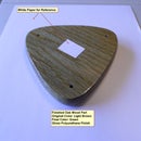
The second image shows the construction of one of the temperature probes set up to measure the air temperature in the hanger. It was just a probe on a short wire and a connector designed to mate to the heater control box temperature probe ports.
Step 5: Connect the Heater Control PC to the Temperature Module


The process of communicating with the Temperature Module requires that the Ethernet port on the Heater Control PC has a few changes to it so that direct communication can occur. The key activity here is that this Ethernet port needs to have its IP address set up manually to work with the IP address that theTemperature module was originally configured to work with.
Referring to the first image for this step, select the Local Area Connections in Windows and then select the Ethernet port connection on the PC being used. (The exact steps will vary slightly for different Windows versions, instructions here are for Windows 7.)
The second image shows the screen for setting the static IP address for this port. In this case I selected 192.168.1.50 with a sub mask of 255.255.255.0 . With this saved it is time to communicate with the Temperature Module in the Heater Control box.
It should be noted that the instruction manual provided by ControlByWeb.com is very good related to the process of interfacing with this Temperature Module.
Step 6: Talking to the Temperature Module From the Heater Control PC


Interfacing to the Temperature Module is wonderfully simple!
#1 Open a web browser and type in the following address (see first image):
http://192.168.1.2 /setup.html
What occurs by using this address is that the browser begins to communicate with the Temperature Module and the setup page of the Temperature Module is shown. (Simple!)
In the webpage view, if you click the tab called ‘Password’, a second web page is shown which allows you to setup unique login values for the password for the setup page as well as for the direct web interface for the controls of the temperature module (ref the second image of this instructions set).
The last image in this instruction step shows an image of what occurs after the username and password has been set for the control page of the temperature module. As shown, the username is ' hanger'. To see this control page of the temperature module the URL used is:
Step 7: Other Temperature Module Setup Tabs


The Temperature module has several other setup tabs worth knowing about.
As noted in this step’s first image, the Network tab allows the user to change the Network parameters. In this project I used the default settings.
In the second image the General Setup page is shown (found under the ‘General’ tab in the main setup page). Within this setup page several setting are defined for this project. I set the temperature module to display data from Sensors 1-3. I also set the control buttons and the 'state' of control relays 1 and 2 to be shown.
The last image of this step, shows the web page when the ‘Sensor 1’ tab is selected. In this screen several options can be set, but for this project the primary item set is the temperature sensor's digital ID. Each of the three temperature sensors of this project have unique IDs so the Temperature Module must be configured for it know which one it is communicating with.
Step 8: Turning the Preheaters ON/OFF Remotely


In this step we finally get to see the fruits of our configuration work!
In the first image is a screen view when the following URL is enter into the browser:
http://192.168.1.2 (recall this is the default address of the temperature module’s control page)
Note that the name of the module is shown as well as the temperature of sensor#1 and also the state and control buttons for the temperature module's internal relays 1&2.
In this case sensors 2 and 3, xx.x is being shown because the temperature probes were not connected yet.
Also note that the relays are in an 'off' state …which means the normally open relays are not closed.
The second image of this step shows what happens when the ON button of relay is clicked on. Relay 1 closes and the state of the relay goes from OFF to ON.
KEY: The above control menu is what is accessed to turn on/off the aircraft preheaters on and off remotely. (more on this in a moment).
The last image of this step shows the Heater Control box schematics again for reference. The key item to notice is that the normally open relay is part of the temperature module. The relay shown, is ‘Relay 1’ which was controlled by the web interface page noted in the instructions above.
Step 9: Connecting and Using the Heater Control PC Remotely From Another PC or Smartphone!

Now for the final step in using the Aircraft Preheater Remotely!
Referring to the associated diagram of this step. VNC (virtual network connection) software is needed on the Remote PC or Smartphone that will be used to connect to the Heater Control PC. The Heater Control PC will also have VNC software installed on it.
Unless you’re an expert in VNC software already, the idea of using such software may seem quite complex. When I was researching the best VNC software to use I realized there is both free and commercial packages to use for this purpose. Some of the VNC packages have security built in and other VNC packages were geared for the UNIX expert. See the following Wikipedia page to illustrate the range of products available:
https://en.wikipedia.org/wiki/Comparison_of_remote...
Ultimately what drove the software selected were the following parameters:
#1 Easy to use and install
#2 Free if possible
#3 Security built in
#4 It would be nice if it worked on my smartphone as well as my home PC
#5 I wanted a VNC software tool that did NOT require me to set up ports on my security router.
Originally I used a VNC tool called remotevnc for this project, see:
https://sourceforge.net/projects/remotevnc/
My final selection for the VNC software is an excellent product called: RemoteUtilities that can be found at: https://remoteutilities.com
This software may be used freely for 10 or less remote connections (please review the product's site for details).
This VNC tool has two pieces of software that are installed. The ‘Host’ VNC portion was installed on the Heater Control PC while the ‘Viewer’ VNC portion was installed on the home PC and my smartphone.
Once installed the ‘Host’ VNC software needs to have a security login password created as well as an ‘internetID’ . These two pieces of information are then used by the ‘Viewer’ VNC software, ( that is running on the home PC or smartphone), to allow a remote connection to occur to the Heater Control PC. Once this connection occurs the ‘Viewer’ VNC application opens a window with a remote replication of the desktop of the Heater Control PC. At this point you have complete 'remote control' of the Heater Control PC… it is just as if you are setting in front of that PC!
Once this remote connection is made, then the next step is to measure hanger temperatures and to turn on/off the preheaters. This is done by opening a web browser (as we did earlier) on the Heater Control PC and then connecting to the web interface of the Temperature module as done in earlier steps.
While remotely connected to the Heater Control PC, it possible to use the USB camera software to view the hanger and aircraft from the USB camera.
Step 10: The Final Reason for the Project

The key reason for this project, as noted earlier, was to have the ability fly in the winter when I want to by having the aircraft's engine preheated and ready to go when I arrived at the airport.
This simple project has saved me many hours of waiting for the aircraft engine to heat up and it has also allowed me the ability to visually check in on my aircraft investment from a remote PC or my Smartphone.
Although this project was specifically related to the aviation field, it should be clear that the method here could be used for all types of remote monitoring and control needs.
I have also attached a short video of a winter takeoff and landing in Ohio in a Cessna 150 aircraft for your enjoyment!
Attachments


Participated in the
Full Spectrum Laser Contest 2016


