

Introduction: Web-controlled Twittering Roomba


I wanted to see if I could operate my Roomba remotely and get it to report its status via Twitter while I was away from home. I also wanted to make the device independent of a computer. This is the solution I came up with and it works very well.
Follow @TheRoomba on Twitter to see what mine is doing!
Step 1: Needed Parts and Tools


- 1x - Small signal, low power PNP transistor (I used a 2N2907A (may also be known as NTE159))
- 1x - 8-Pin mini DIN male connector
- 1x - 7805 5V voltage regulator
- 1x - Solderless breadboard
- 1x - Arduino board
- 1x - Sparkfun WiFly Arduino shield
- Row of five or more male pin headers
- A short piece of Cat5 cable or similar wire (Cat5 is 24 AWG)
- And last but certainly not least, a Roomba*
Tools:
- Soldering iron
- Small scissors
- Third hand
- Hot glue gun
- Multimeter
Assumptions:
- For the purpose of this Instructable, I am going to be assuming that you have a basic knowledge of basic electronics, the Arduino and the Arduino's programming language.
*I have only tested this with the 500 Series. However, it should work with newer models, but I am not sure about older models.
Step 2: Roomba's Serial Connector
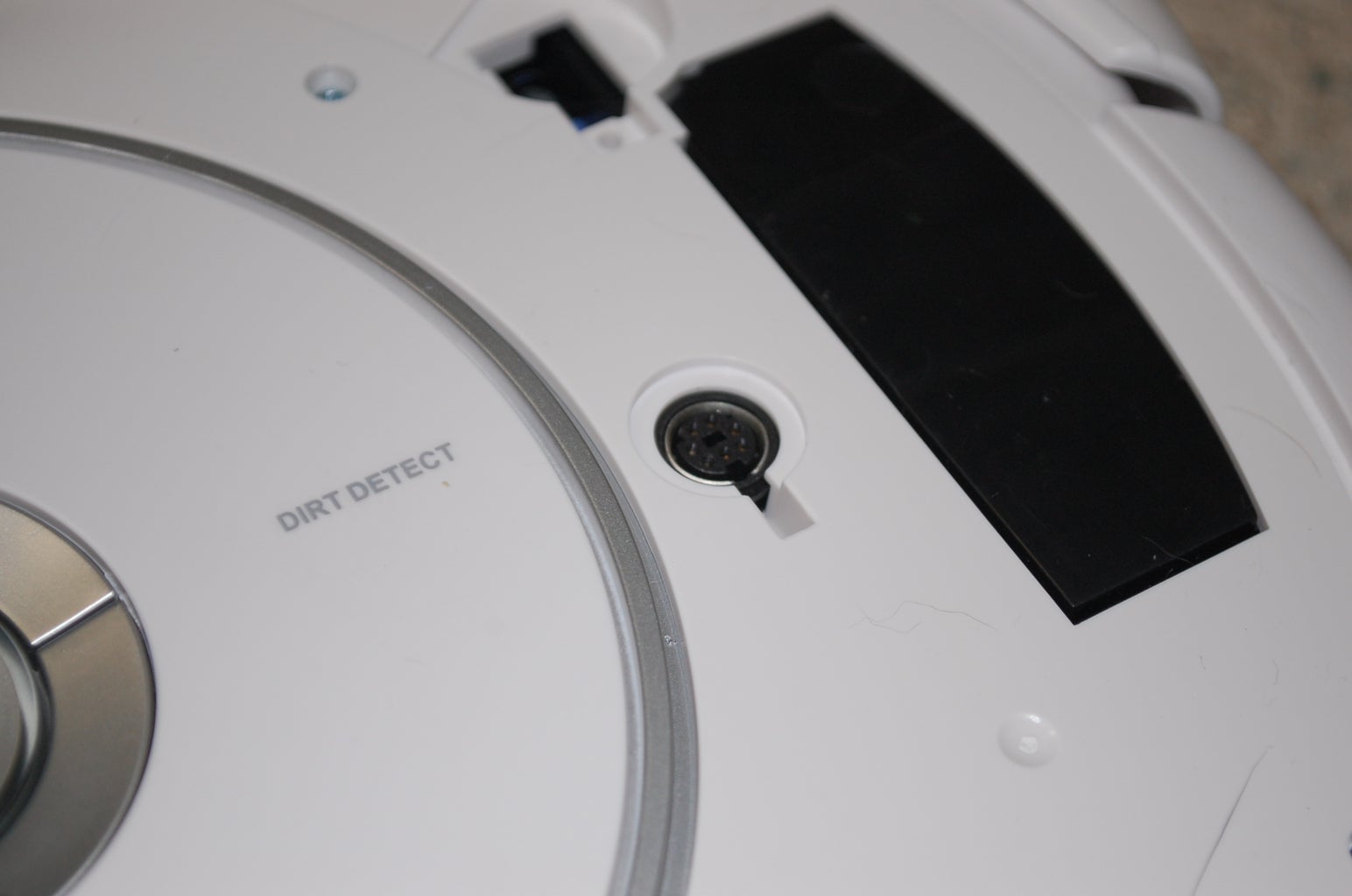


All 500 series Roombas have a serial connector on them. We will be using this serial port to control and read sensor data from the Roomba. The serial connector is simply an 7-pin Mini-DIN jack with the block in the center. You can usually purchase these for a few dollars at your local electronics store.
To access the serial connector: remove the bin, gently pull up on the back edge of the top plate until the two clips in the back release. Now, use a flat blade screwdriver to gently pry up the rest of the plate. The connector is to the right of the control buttons.
You may wish to drill a hole in the plate to access the port without the plate removed.
Step 3: Creating a Connection Cable


The easiest way to connect to the serial port is to create a short cable using an 8-Pin mini DIN connector, some male pin headers and a short length of Cat5 cable. You may use a 7-Pin mini DIN instead if it has the plastic block in the center and not the bottom as the center pin is not connected. Strip a small amount of insulation off of the individual wires. If you don't have a wire stripper that can strip wires this small, gently rotate a pair of scissors around the insulation and pull it off.
It may be tricky to solder the wires into the small cups of the mini DIN connector. Use your Third Hand to hold the wire and mini DIN connector. You may wish to place the wire between a small piece of folded paper to prevent teeth marks from the Third Hand. Work form the inside out. If the wire is soldered in the cup properly, you can use a solder vacuum to clean up an excess solder on the exterior of the cup. Make a chart of what cup you attached each wire to.
Use a multimeter to check for shorts between pins.
The pins may be bent slightly out of place. Insert the pins into the Roomba's connector to realign them.
Use some hot melt glue between each wire so the do not bend and short against each other. Wrap some tape around all the wires to prevent shorts against the case. Reassemble the mini DIN connector, but do NOT slide the outer case of the mini Din over the pins until functionality has been verified. This will make it easier to modify if necessary. Strip the other end of the wire. Pins 6 and 7 (see image below) are both ground; attach them to the same pin header. Pins 1 and 2 are both positive. The voltage on these pins varies. When docked, it is about 20V, otherwise it is the voltage of the battery (about 14V). Attach them both to the same header. Attach the rest of the wires to their own headers.
Step 4: Connecting the Arduino


Place the WiFly shield on the Arduino.
Attach the cable by connecting the mini DIN connector to the Roomba and the pin headers to the breadboard.
Use the wiring diagram that you created in step 3 to help you connect the wires properly for the instructions below.
In his write up of the Roomba library for the Arduino, Mike McCauley tips us that we must use a PNP transistor in order to trigger the Arduino's RX pin from the Roomba. Use a jumper to connect the Roomba's TX pin of the cable to the Base pin of the transistor. Connect the Collector pin of the transistor to ground and the Emitter pin to the Arduino RX.
Attach the Arduino's TX pin to Roomba's RX pin on the cable. Attach the ground pin from the cable to the Arduino's ground.
Next we have a slight problem. The Roomba's power output can be up to 20V when it is being charged. While the Arduino's voltage regulator can handle this, the WiFly 3.3V voltage regulator cannot. We will need to add our own voltage regulation circuit to the breadboard. To do this we use a 7805 voltage regulator to bring the voltage down to 5V. Connect the Ground of the 7805 to ground, the Vin pin to the Roomba's power, and the Vout to the 5V pin on the Arduino.
When you attach the connector to the Roomba, the Arduino's power LED should light up.
Click here for a larger version of the Breadboard diagram.
Remember to disconnect the cable from the Roomba before reprogramming the Arduino!
Step 5: Complete Code

You can download and contribute to the code at GitHub. It may be a little buggy, so please feel free to comment any suggestions for improvement, or contribute yourself.
In order for it to work, you will need to replace "TWITTER oAUTH KEY" with the oAuth key created in Step 8 "Programming 3: Twittering". Then we just need to set the router passphrase and SSID. All of these options may be found in the "Credentials.h" file. The Arduino should now be able to access your network and your Twitter account. The code is also well commented so you should be able to modify several of the values easily, including what the Roomba says for certain events.
If you have any difficulties, scroll down to Step 9: Troubleshooting for help or feel free to contact me.
Make sure you have the Roomba Library(Step 6), the Twitter Library (Step 8), and the WiFly Library available from SparkFun.
Step 6: Programming 1: Communication
Communicating with the Roomba is actually fairly simple. The Roomba's serial port uses iRobot's Open Interface (OI) protocol to communicate with other devices (such as the Arduino). While the OI can provide full control of the Roomba's motors and LEDs, it can also be used to begin the built in cleaning process, which would undoubtedly take several hours to recode into the Arduino.
Instead of writing Arduino code to interface with the OI ourselves, we will use the fabulous library by Mike McCauley for interfacing with the OI. (Thanks Mike!) Mike's library features every basic OI command for the Roomba.
Full details of iRobot's OI can be found here.
Step 7: Programming 2: Web Control

For this, we can stick mostly to the example code for the WiFly web server. The example code provides us with everything we need to do except reading the requests from a web browser. However, this is pretty easy to add. All we need to do is read the request byte by byte using the sample code and place that in a string. Fairly easy right?
The hard part of this is configuring the router correctly. Firstly, we need to tell the router to give the WiFly Shield a static IP address. Unfortunately, since all routers are different, I cannot tell you how to do this. You will need to look in your router's manual for instructions on how to assign a manual IP address.
Unless you don't mind other people potentially controlling your Roomba, this is mostly for control over the network and not the internet. However, if you understand the security risks (or know how to set up an authentication system), it is possible to configure most routers to forward to the Arduino web server. Again, you will need to look in your router's manual on how to do this. You may also be able to find instructions using Google.
To control the Roomba over the network, simply enter the IP address you assigned to the WiFly into you browser's address bar and voila! If you did connect it to the internet, you can access it anywhere by entering the IPv4 address of your router, which can be found here.
Step 8: Programming 3: Twittering

This part of the code was a little more difficult than I originally anticipated. Most guides for adding Twitter to the Arduino require a computer to do the actual Tweeting. I did not want to need my computer turned on to receive updates from the Roomba. There is, however, another excellent library (by @NeoCat) that we can use to make the Arduino Tweet without the assistance of a computer. However, the library is designed specifically for the Ethernet shield. Fortunately, though, Sparkfun's library for the WiFly shield is designed to easily replace the Ethernet shield library with minimal code tweaks. I have packaged a modified version of the Twitter Library with the code download. Don't worry about installing it in your libraries folder.
We now have a Twitter library that is fully compatible with the WiFly shield. In order to start using the library we will need to allow it access to our Twitter account by clicking Here and then clicking "Get a token to post a message using OAuth". Once we have granted it access, we will see a webpage with what is called an oAuth key. All we need to do now is place this in "Credentials.h" file where noted. We can now start Tweeting with the Arduino!
However, here we hit another snag: we cannot tweet something that we have already tweeted in the past. So, the Roomba will only be able to tell you that it has finished once. There are few ways to get around this:
Add a Real Time Clock (RTC) to our hardware and add the time to the beginning of each Twitter post. This method is more expensive, but will look prettier on the tweets.
-OR-
Read a couple of sensor values from the Roomba to generate a random number. This method is less expensive, but it does not look quite as nice as using an RTC to time-stamp the tweets.
-OR-
We could also use the Arduino's millis() function to tag on to the tweet. This is the most reliable and the easiest. However, it will also look ugly compared to the RTC time-stamp.
For this Instructable, we will be using the latter as it is the least difficult and least expensive. The millis() function returns the number of milliseconds since the program was started. We do not need to worry about the number getting too long as it resets to zero after fifty days. The highest the number may be is about 4.32x10^9, which is ten digits. As for it resetting, we do not need to worry about duplicate tweets as the likelihood of an exact match is near impossible.
Step 9: Troubleshooting
This is a small section about the problems that I ran into and how I fixed them.
Issue - Possible Solutions
WiFly does not connect - Confirm your SSID and router passphrase in the Credentials.h file
If you are using WEP, try changing to WPA/PSK+WPA2/PSK
Twitter does not update - Confirm that your oAuth key is correct (see Step 8)
Check your solder joints
Web control page does not show correct information - Check your solder joints
Cannot access web control page - Ensure that you are using the right IP address (see Step 7)
If none of these solutions helped you, please feel free to contact me.
Step 10: Conclusion
I hope you liked my Instructable and hope you may find it useful!
There are many ways that I considered furthering the code. Including:
* Driving it around manually.
* Adding Cosm support to log cleaning times, battery-life, etc.
* Moving the components onto a PCB instead of using a the breadboard.
Please comment any questions or suggestions. I welcome your feedback.

Runner Up in the
Adafruit Make It Tweet Challenge

Participated in the
Make It Move Challenge

Participated in the
Microcontroller Contest


