

Introduction: Wedges for Drill Chuck Removal


How do you remove a stuck drill chuck? Well, if it has a machine taper fitting, with a pair of thin steel wedges called, surprisingly enough, drill chuck removal wedges. What if you do not have such contraptions at hand? It is not difficult to make a pair of wedges, and you are in business.
I was cleaning up a drill press I recently acquired, and wanted to remove the chuck to inspect and lubricate the spindle, the quill, and the chuck itself.
When I tried the available chuck release mechanism (more on this later), I discovered the chuck was seriously stuck. A pair of chuck removal wedges was needed, but I had none, and none was easily obtainable in the right size.
So I made a pair, and came on the idea of writing down how they work, how you can make your own pair to suit the job at hand, and how to use them properly.
Step 1: When Do I Need Wedges?

The when is very important, because using wedges when they are not called for will get you into serious trouble.
Wedges are used only and only if your drill chuck is mounted using a machine taper. A machine taper is a kind of fitting where the male has the geometry of a cone frustum (informally, a cone without the pointy end). The female (socket on the chuck side) has a matching cone frustum geometry.
Machine tapers are used, mainly in drill presses, to hold drill chucks in place by friction only. There are several types of machine tapers, the most common ones encountered on drill chucks being Jacobs, Morse, and B-tapers. Which taper you have has an influence on the size of the wedge pair you need, not on their workings. By the way, this is often a good reason to make a pair, as the size of the ones you may have or be able to get may not fit the taper/spindle size.
A drill chuck can be mounted directly on the spindle, or on an arbor adapter. For a drill press this is often a Morse taper arbor, as shown in the figure.
A Morse taper arbor has a short taper like a Jacobs or a B16 on one side (for the chuck), and a Morse taper on the other side (for the spindle). If your chuck is mounted on an arbor, this discussion applies to separating the chuck from the arbor. Separating the Morse taper arbor and chuck together from the spindle is done differently, using a single wedge that is inserted in an opening through the lowered quill and the spindle, allowing to put pressure on the tail of the Morse taper.
An alternative way of mounting a chuck is by using a male thread on the spindle (and of course a matching female thread on the chuck). This is common on portable drills. Never try to use wedges on a threaded chuck. It would be like trying to remove a nut from bolt by pulling on the nut! You will definitively break or damage something.
Step 2: How Do Wedges Work?


A wedge pair works like in the drawing, where one of the wedges is made transparent for clarity. When symmetric forces are applied along the direction of the white arrows, the wedges are forced against each other, and the presence of the bevels results in forces directed as the red arrows that push outwards,
Wedges are used to apply an axial force (with respect to the spindle rotation axis), which has the effect to loosen the taper fitting, so that the chuck conveniently drops off. Be careful, for if the chuck was really stuck on your spindle, it will pop off with force. It is a good idea to wear eye protection (especially if you are inches away looking closely and wondering why it is not coming loose), and to put something soft like a cloth on your drill press table to catch the ejected chuck.
Always use two matching wedges, and apply pressure gradually using a vice. A machine vice that is light enough to be held in your hand and that has a jaw opening large enough to accommodate the wedge pair will be fine.
Never use a single wedge and a hammer. The sideways blows on your spindle bearings will not improve the quality of your drill press, or of your machining!
Step 3: Making the Wedges


On a milling machine, it is quite simple to make the wedges:
1. Square two rectangular steel work pieces of appropriate size. Thickness is the most critical dimension here, as the completed pair needs to fit between chuck and spindle/arbor shoulder with enough overlap.
2. Mark and drill two holes to get the slots started (this is not strictly necessary, just saves time – drilling is faster than milling).
3. Mill the bevel. Now for this it is important that the bevels on the two work pieces have the same angle, so they are best machined in one go. The simple setup you can see in the photos works well as long as you mill along a path parallel to the long side of the vise. This way the cutter will push against the vise jaw, not parallel to the vise jaw, which is likely cause the work piece to move.
What if you don’t have access to a milling machine? The old file will do it, although in this case you really need to have a setup that allows you to file the two bevels in one go. Unless you are really good with a file, I would also advise some sort of jig to make sure the bevels are come out really nice flat. I know I would need one…
Notice that the bevels have to be accurate not only because accuracy and symmetry are beautiful things, but also because you want the two opposite surfaces of the wedge pair to be parallel, in order for the separation force to be coaxial with the spindle or arbor.
Step 4: Using the Wedges


Finally, we are good to go. Two simple steps are left:
1. Position the wedges in working position between the chuck and the shoulder of the spindle or arbor.
2. Apply pressure as per the red arrows in the photo. The best way of doing this is by using a vice light enough to be hold in position by hand. Pressure needs to be increased gradually and symmetrically.
3. Chuck pops off. Proper job done, and time for coffee!
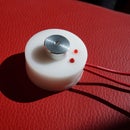
Wait a minute… what is that lock nut in the picture? Well, funnily enough, on my drill press this locknut is the ACRM (Available Chuck Release Mechanism), i.e. it is there to make the use of wedges unnecessary…
The idea is that you turn the lock nut, and the nut comes down against the chuck, pushing it off the spindle. Did I not understand it was that simple?
No. In theory, great idea.
In practice, the amount of downward pressure you manage to put on the chuck by turning the lock nut with a small c-spanner won’t pop off a chuck that is really stuck there, like mine was.
The culprit was, as it is often the case, dry oil residues that had find their way into the taper fitting. You can see the residues in the first photo, they look like rust spots. After a good cleanup with solvent, the chuck went on again with a light tap, and now the locknut works as intended.
Happy drilling!


